Para agregar el frente de calle GDS3710 en NVR Epcom, sigue estos pasos:

Paso 1: Preparar el GDS3710 para la conexión

  1. Conéctate al GDS3710 a través de un navegador web utilizando la dirección IP predeterminada 192.168.1.168.
  2. Inicia sesión con las siguientes credenciales:
    • Usuario: admin
    • Contraseña: La contraseña debería estar impresa en el dispositivo.
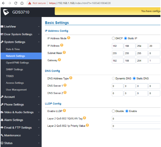
  3. Una vez dentro de la interfaz gráfica del GDS3710, ve al menú “System Settings” (Configuración del sistema) y luego selecciona “Network Settings” (Configuración de red).
  4. Asigna una dirección IP fija al GDS3710 dentro del segmento de red que proporcionará el NVR. Esto asegura que la cámara y el NVR estén en la misma red. Guarda la configuración.
Paso 2: Configurar el NVR

  1. Accede a la interfaz gráfica del NVR. Puedes hacerlo a través de la dirección IP del NVR o conectando una pantalla al NVR a través del puerto HDMI.
  2. Ve al menú de configuración del NVR, que generalmente tiene un ícono de una rueda dentada.
  3. Luego, selecciona “Camera IP” (Cámara IP) o una opción similar en el menú del NVR.
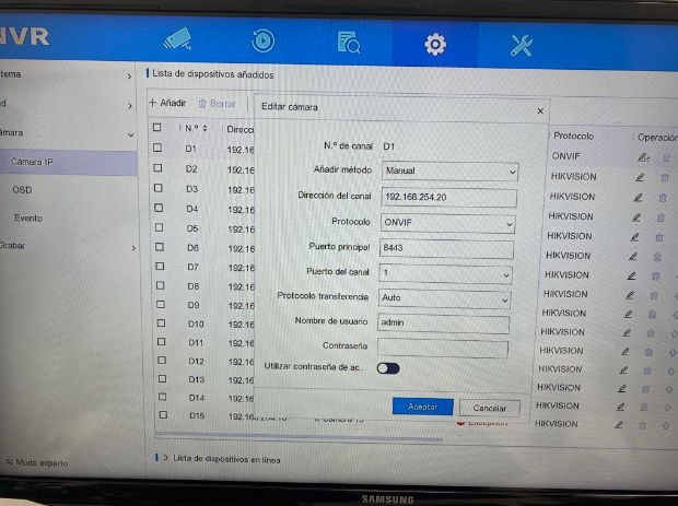
  4. Haz clic en el botón “Editar” (que generalmente se parece a un lápiz) en uno de los canales disponibles donde deseas agregar la cámara GDS3710.
  5. Selecciona el método de adición como “Manual”.
  6. Ingresa la dirección IP que configuraste en el GDS3710 en el campo correspondiente.
  7. Selecciona el protocolo “ONVIF” (asegúrate de que la cámara GDS3710 sea compatible con ONVIF) y proporciona la contraseña que configuraste en el GDS3710.
Paso 3: Revisar el resultado

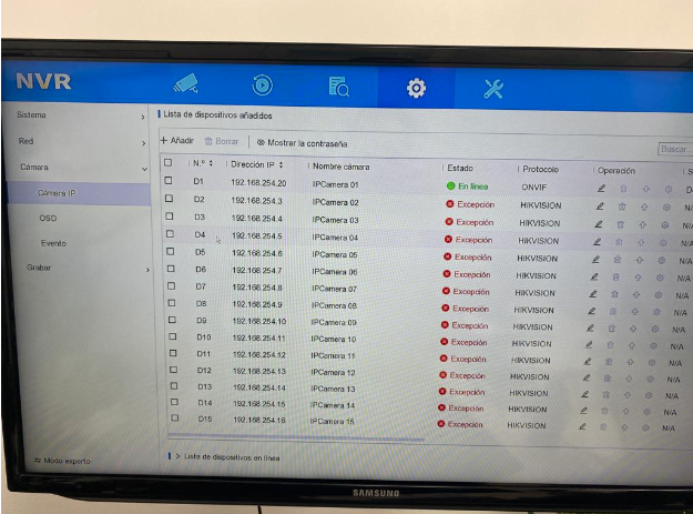
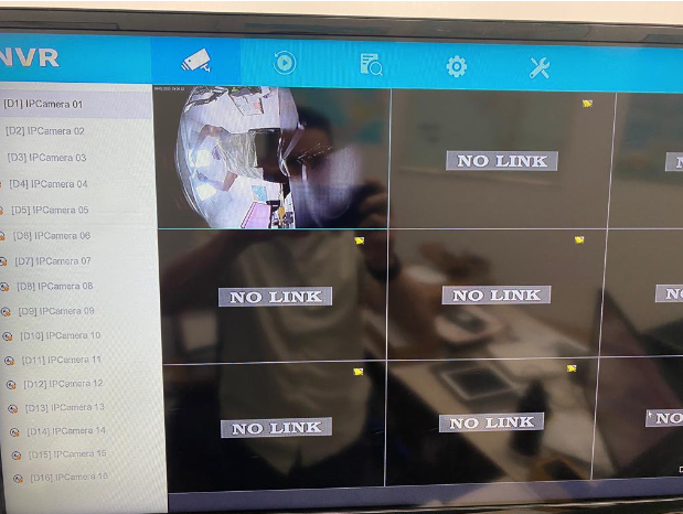
Una vez que hayas completado estos pasos, el GDS3710 debería quedar registrado en el NVR como una cámara adicional. Puedes verificarlo al acceder a la vista en vivo del NVR y seleccionar el canal donde agregaste la cámara GDS3710. Deberías poder ver la transmisión de video desde la cámara en el NVR.

Asegúrate de que la dirección IP y la contraseña sean correctas y de que ambos dispositivos estén en la misma red para que la configuración funcione correctamente.
Adding GDS3710 Door Phone to Epcom NVR

Step 1: Prepare the GDS3710 for Connection

  1. Connect to the GDS3710 through a web browser using the default IP address, 192.168.1.168.
  2. Log in with the following credentials:
    • Username: admin
    • Password: The password should be printed on the device.
  3. Once inside the GDS3710’s graphical interface, navigate to the “System Settings” menu and select “Network Settings.”
  4. Assign a static IP address to the GDS3710 within the network segment provided by the NVR. This ensures that the camera and the NVR are on the same network. Save the configuration.

Step 2: Configure the NVR

  1. Access the NVR’s graphical interface. You can do this through the NVR’s IP address or by connecting a monitor to the NVR via the HDMI port.
  2. Navigate to the NVR’s settings menu, typically represented by a gear icon.
  3. Then, select “Camera IP” or a similar option in the NVR’s menu.
  4. Click the “Edit” button (usually resembling a pencil) on one of the available channels where you want to add the GDS3710 camera.
  5. Select the addition method as “Manual.”
  6. Enter the IP address you configured on the GDS3710 in the corresponding field.
  7. Choose the “ONVIF” protocol (ensure that the GDS3710 camera is ONVIF-compatible) and provide the password you set on the GDS3710.
  8. Save the configuration.

Step 3: Review the Result

Once you have completed these steps, the GDS3710 should be registered on the NVR as an additional camera. You can verify this by accessing the live view on the NVR and selecting the channel where you added the GDS3710 camera. You should be able to view the camera’s video feed on the NVR.
Ensure that the IP address and password are correct, and both devices are on the same network for the configuration to work correctly.

Hikvision/Video Intercom – Configuring a Door Station for 2nd Generation IP Monitors via IVMS4200

In this technical guide, we will explain the configuration of two monitors and a door station from the new generation of Hikvision video intercom systems.
Before beginning, it’s important to verify and/or perform the following steps:

  1. Ensure all devices, including the computer, are connected to the same network (within the same network segment).
  2. Update both the door station and the monitors to the latest firmware version.
  3. Activate and add the devices to IVMS 4200 version V3.1.1.13 and confirm that they are online.

Note: Updates and software can be downloaded from our portal https://www.epcom.net. Once the devices are updated, it’s necessary to restore them to factory settings to apply the firmware update values.

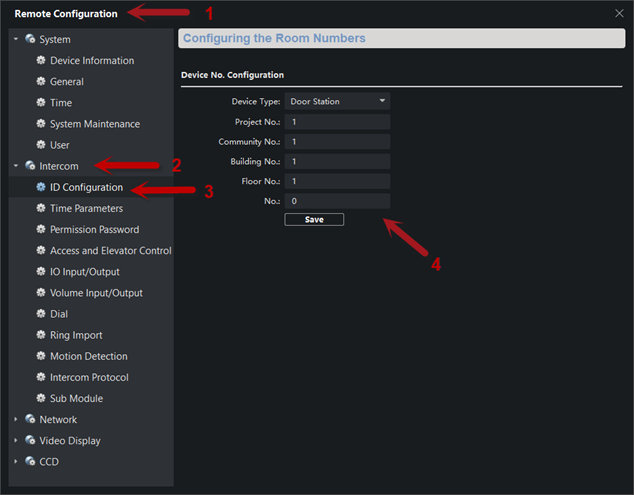
Step 1: Access Remote Configuration (1) on the door station DSK-D8003-IME1 –> Intercom (2) –> ID Configuration (3). Verify that the parameters are set as follows (4).

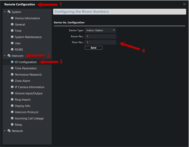
Step 2: Access Remote Configuration (1) on the monitor DSKH-6320-WTE1 –> Intercom (2) –> ID Configuration (3). Under Device Type, select “Indoor Station.” Assign the room and floor numbers; for example, set both as 1 (4).

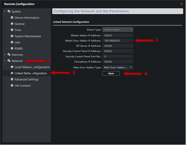
Step 3: Next, in the Network tab (1), select Linked Network Configuration (2). In the (Main) Door Station IP Address (3) field, enter the IP address of the door station. Save the changes (4).

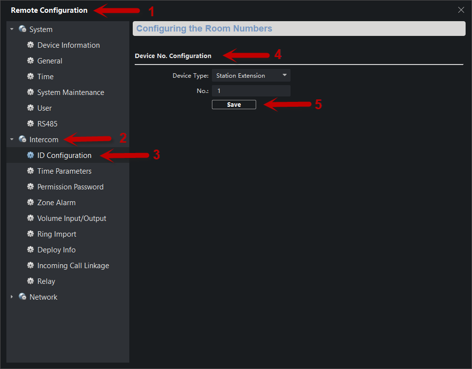
Step 4: Access Remote Configuration (1) of the second monitor DSKH-6320-WTE1 –> Intercom (2) –> ID Configuration (3) –> Device No. Configuration. Select the Station Extension tab and assign the extension number (4). Click Save.

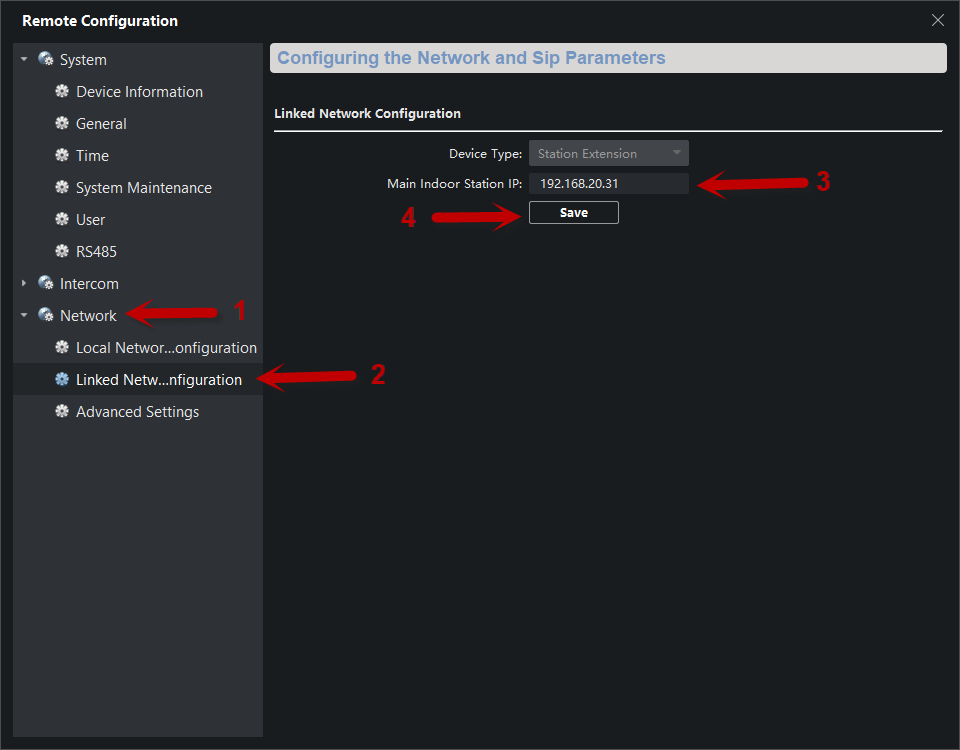
Step 5: In the Network tab (1), choose Linked Network Configuration (2). In the Main Door Station IP Address field, assign the IP address of the main monitor (3). Save the changes (4).

With these simple steps, the video intercom system can make calls to both monitors.

How to enable audio via Coax. on an EV4016TURBOGEN3 DVR

In this post, we are going to explore how to enable camera audio on your DVR via coaxial cable. This configuration can only be done locally on the DVR this option is not available online.

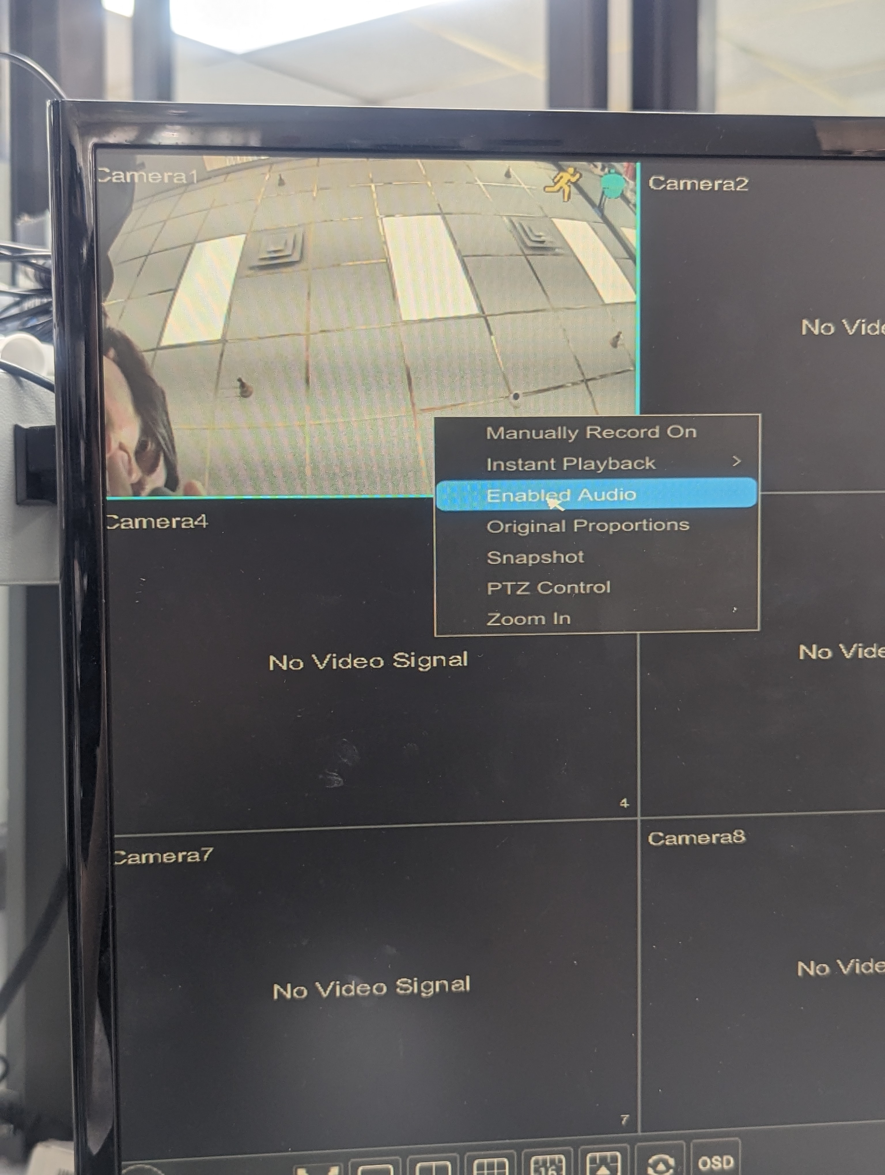
Step 1: Ensure that your camera has the option for “Enabled Audio”.

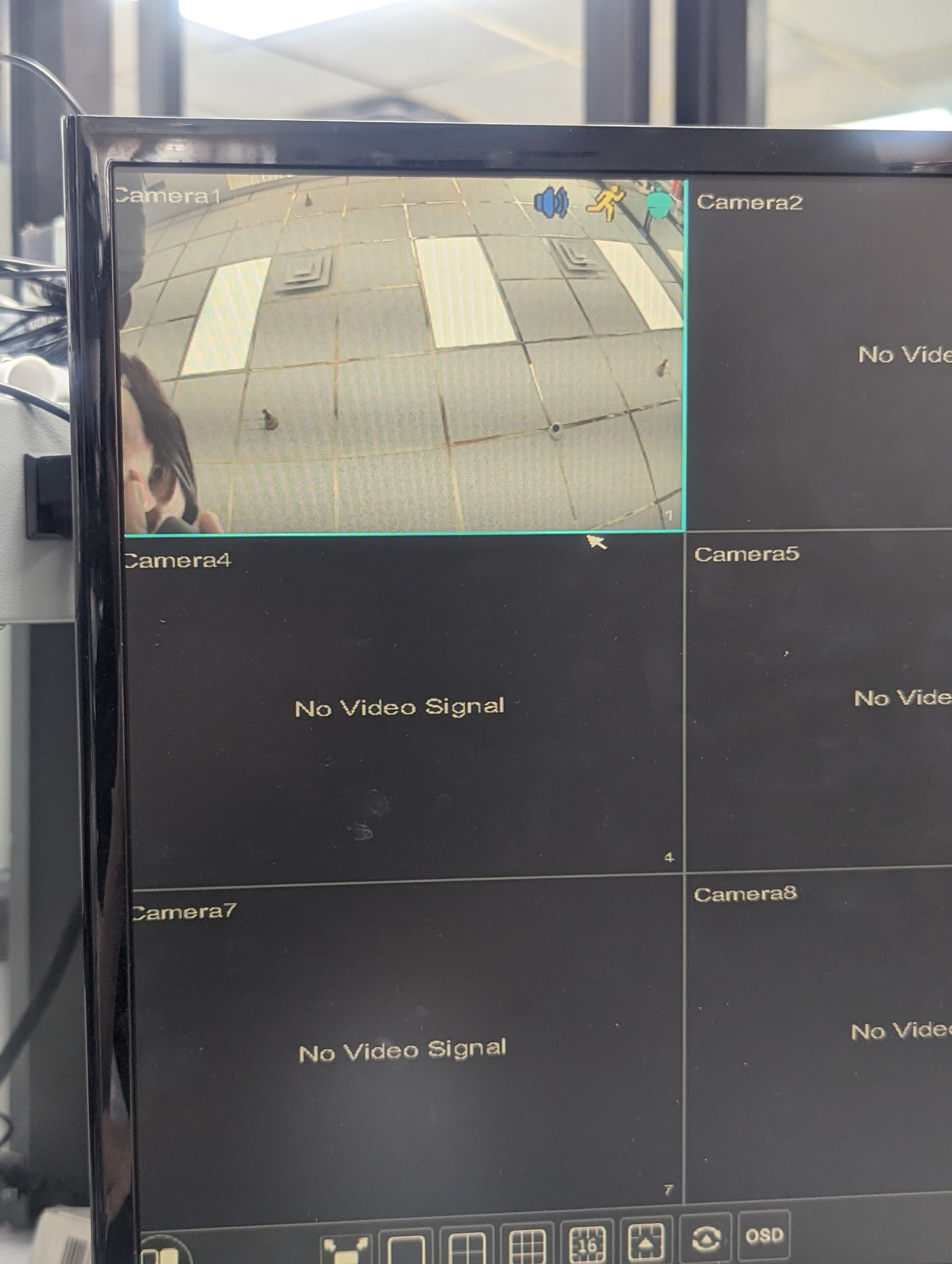
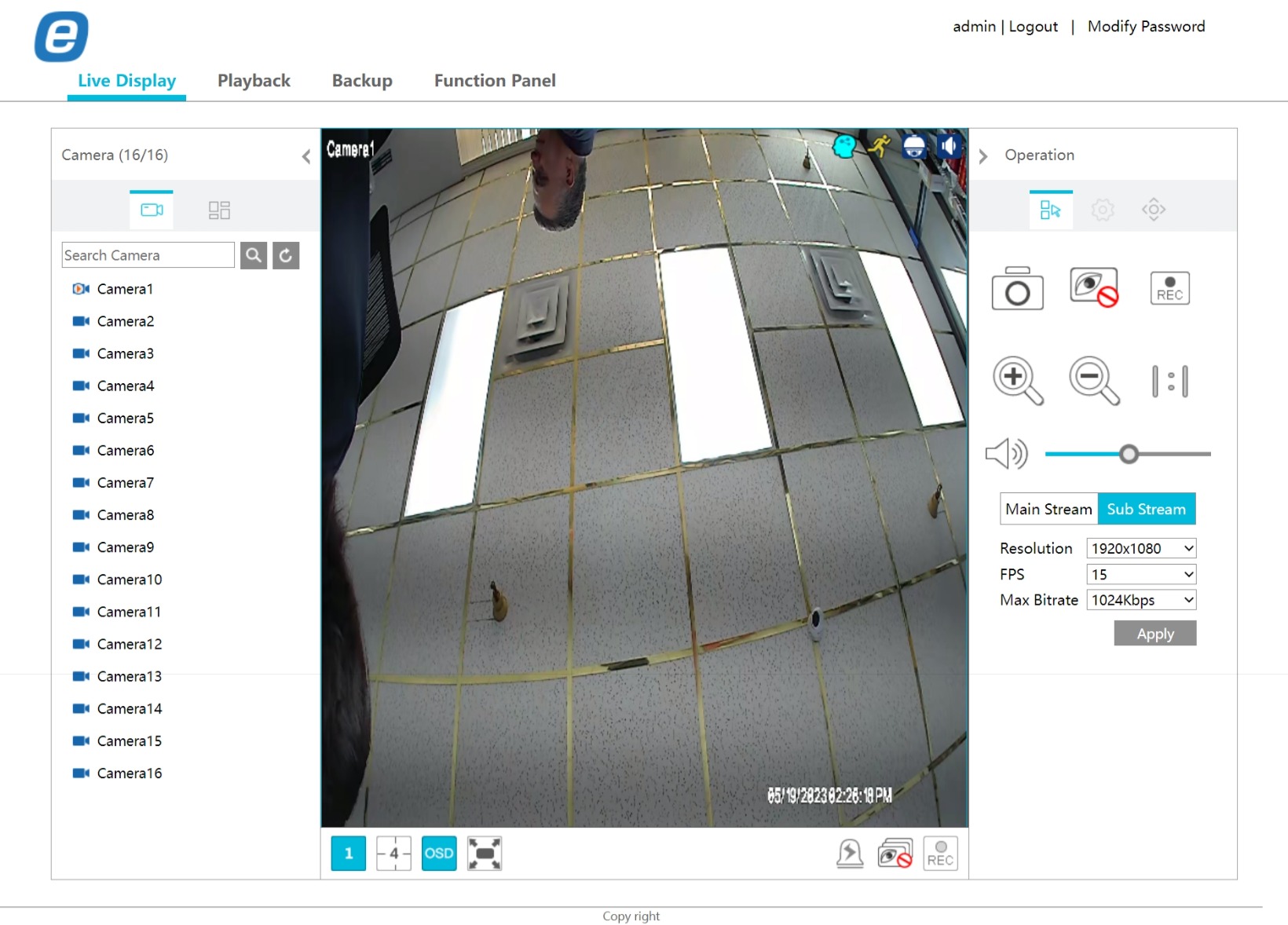
If the audio is enabled, you can see the blue speaker icon appear.

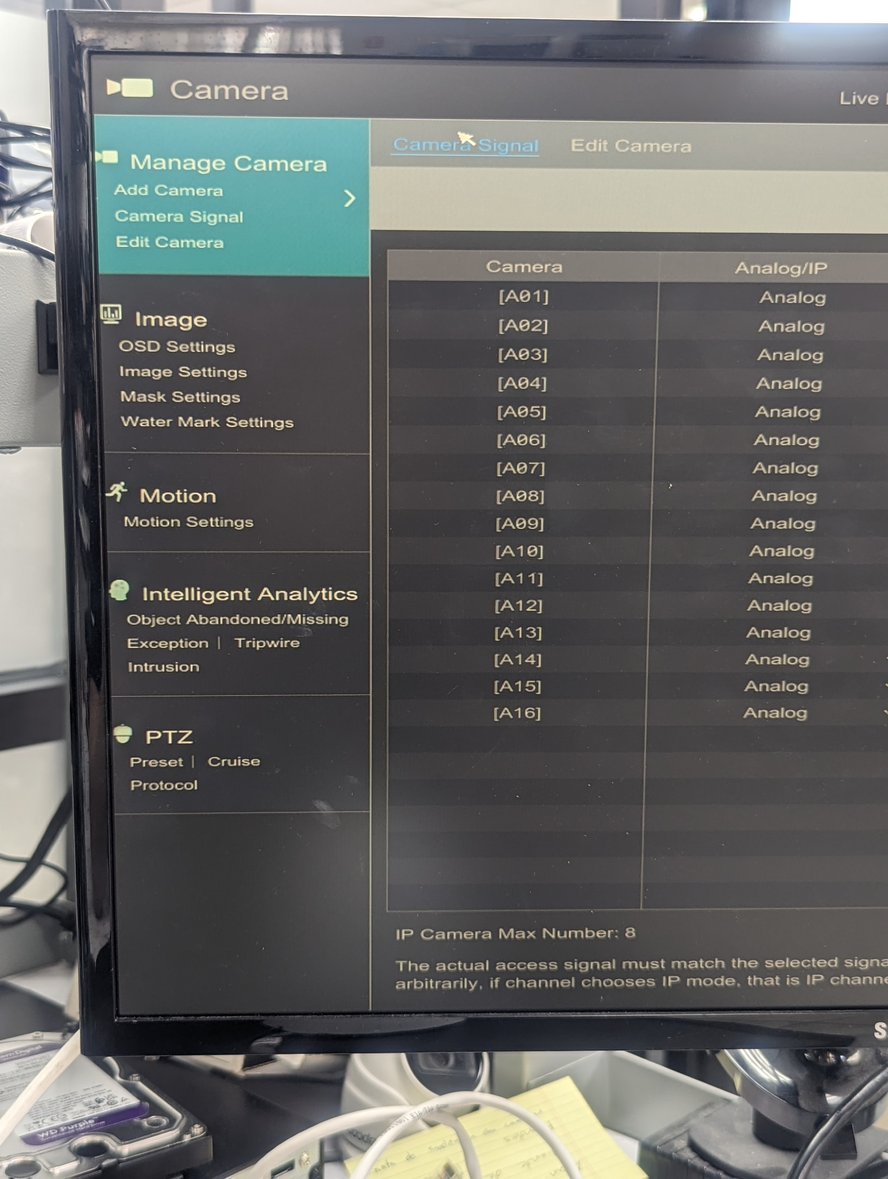
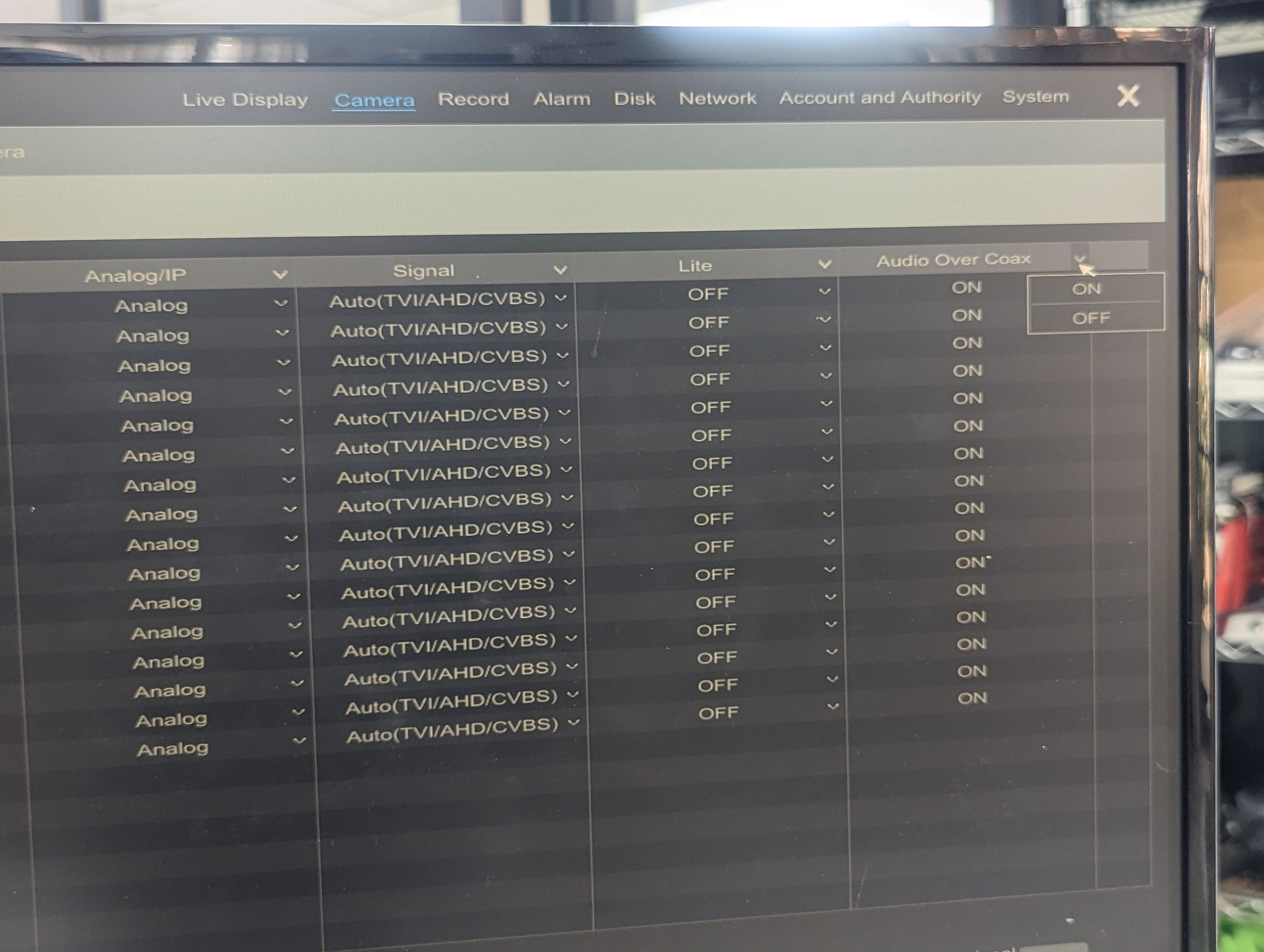
Step 2: Go to the camera section and click on camera signal

Step 3: Once in camera signal ensure Audio over Coax is ON, you can configure this option by clicking on the arrow.

Step 4: Viewing the camera online on Live Display make sure the volume is activated, you should be able to listen to the audio. With this your audio configuration is done.

Note: Two-way audio is only possible in IP devices.

ACM63WT Display and ACVP61W Door-Phone: A Comprehensive Connection Guide

Welcome to the connection guide for the ACM63WT displays and ACVP61W door-phone. This guide will walk you through the process of connecting these devices using a PoE switch connection. By following the steps outlined in this guide, you will be able to activate your ACM63WT displays and ACVP61W door-phone and visualize them on the IVMS-4200 software.

Please note that this guide assumes that you have access to a PoE switch and that your devices have already been given IP addresses on the same IP segment.

With that said, let’s get started and connect your ACM63WT displays and ACVP61W door-phone to your network for optimal performance.

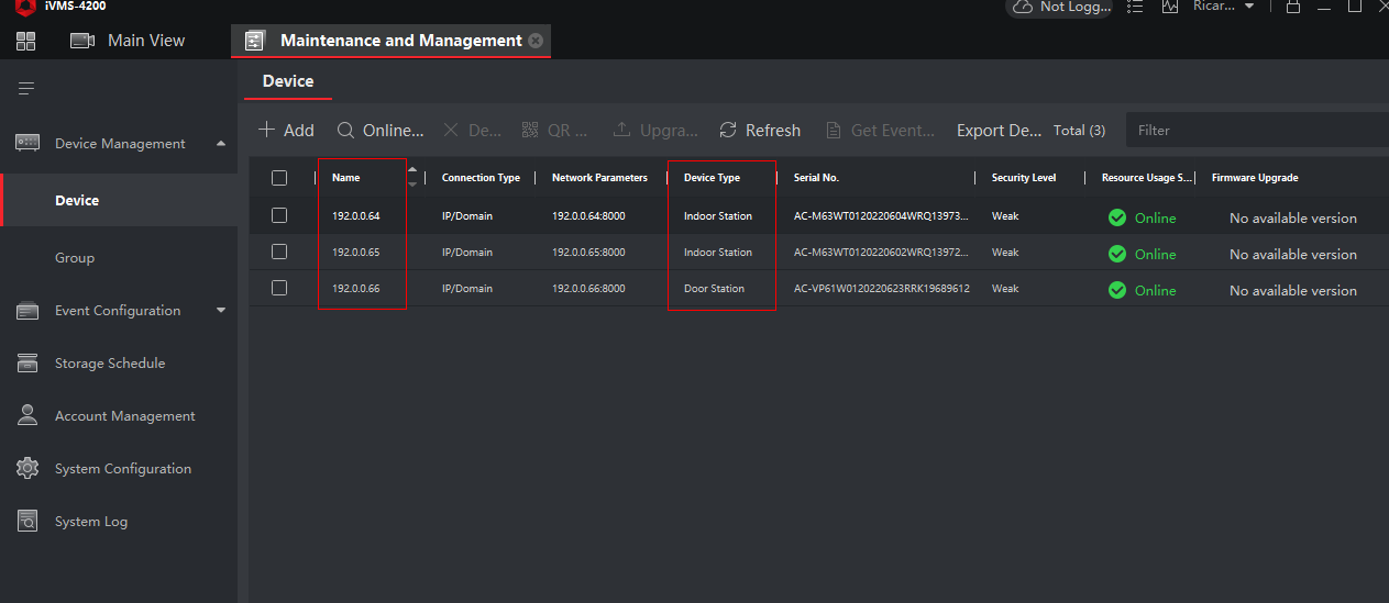
IVMS-4200 activated devices

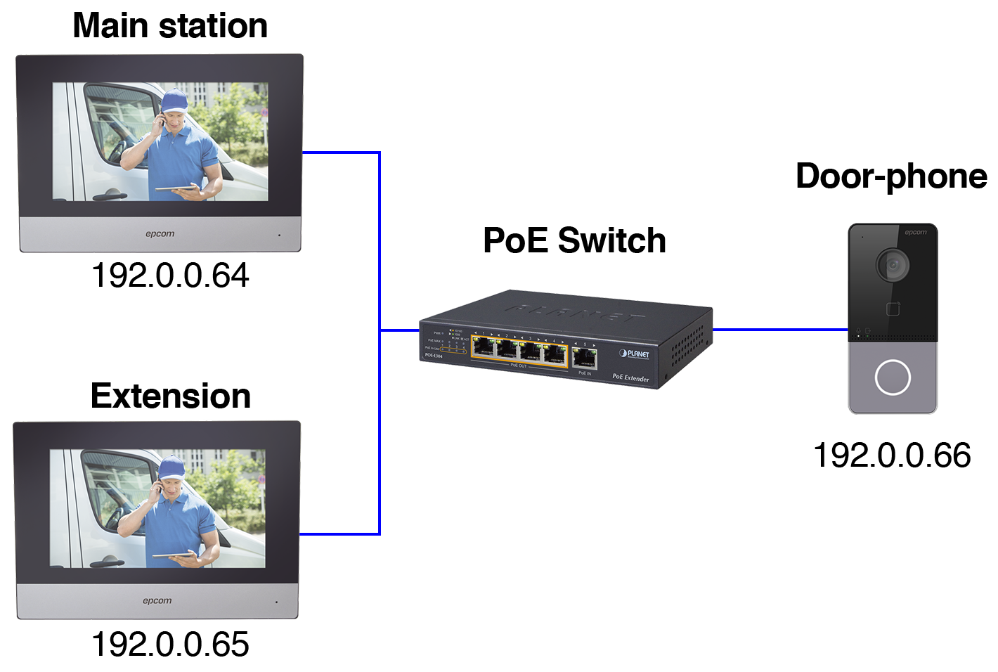
Here is a connection diagram showing the IP addresses of the devices to help you visualize how they are connected to the network.

Device connection diagram with PoE.
  • Main station display: 192.0.0.64
  • Extension display: 192.0.0.65
  • Video door-phone: 192.0.0.66

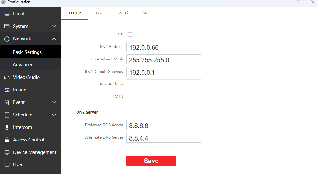
This is the configuration of our video door-phone. We are checking our IP address (192.0.0.66) we will have to check on the main indoor station that they match.

Basic settings, video door-phone IP network settings in the image, the MAC address, and MTU have been hidden.

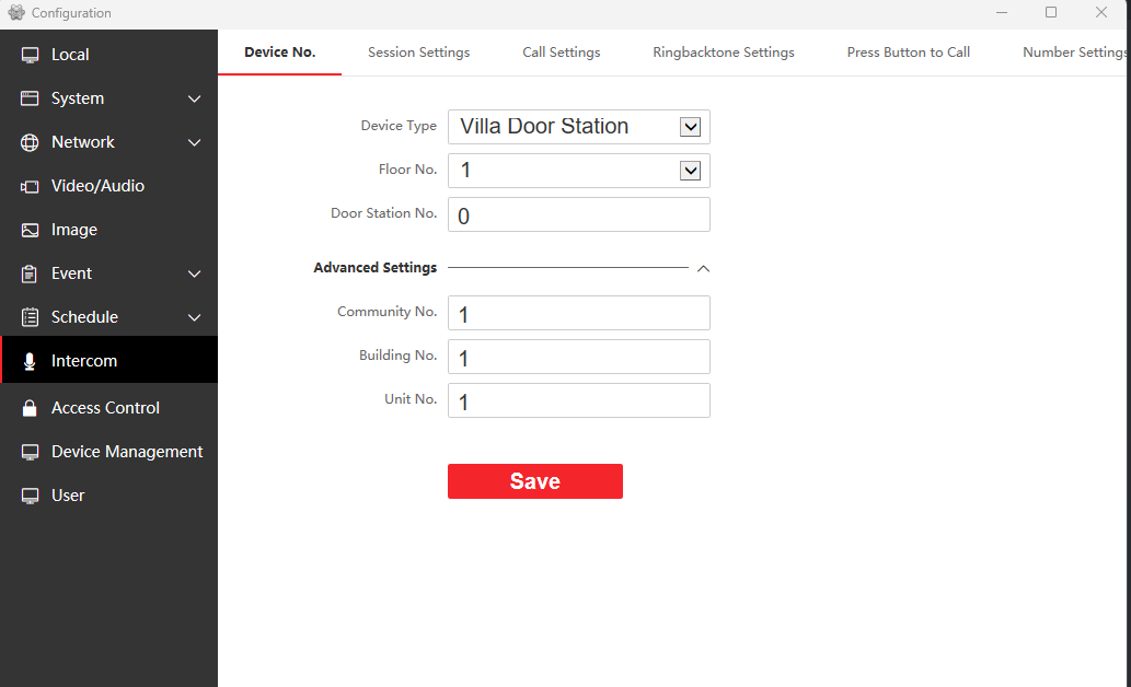
Check that the settings are the same on the intercom tab.

Video door-phone intercom settings

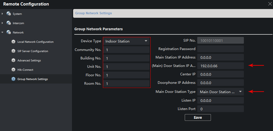
These are the settings for our main indoor station; check that the settings on the red box are the same.

Check that (Main) Door Station IP Address matches your door-phone IP address (in this example, 192.0.0.66). Also that your Main Door Station Type matches the option shown in the image.

Group network settings for the main indoor station

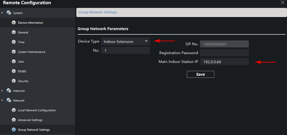
Check the settings of your ACM63WT extension, that Device Type matches Indoor extension and that Main Indoor Station IP matches your main ACM63WT IP address (192.0.0.64).

Group network settings for the indoor extension

M2M – Reactivating devices from the management platform (REACTIVAM2M)

Steps to add a REACTIVAM2M to an M2M device in the management platform (https://m2mservices.com/Admin)

These steps work for all M2M family devices that require reactivation to add their corresponding annual fee.

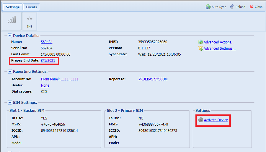
If the communicator is already suspended and inactive for longer than its PREPAY END DATE, the platform will display the “ACTIVATE DEVICE” option.

First, we need to search for the communicator, double-click on it, and go to the home page.

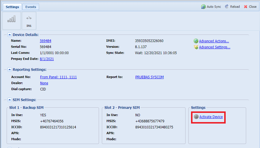
To activate it, we need to click on “ACTIVATE DEVICE.”

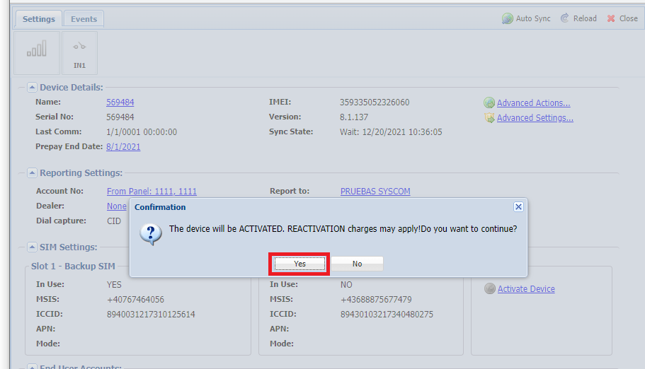
It will ask us if we want to add a REACTIVAM2M, to which we say yes.

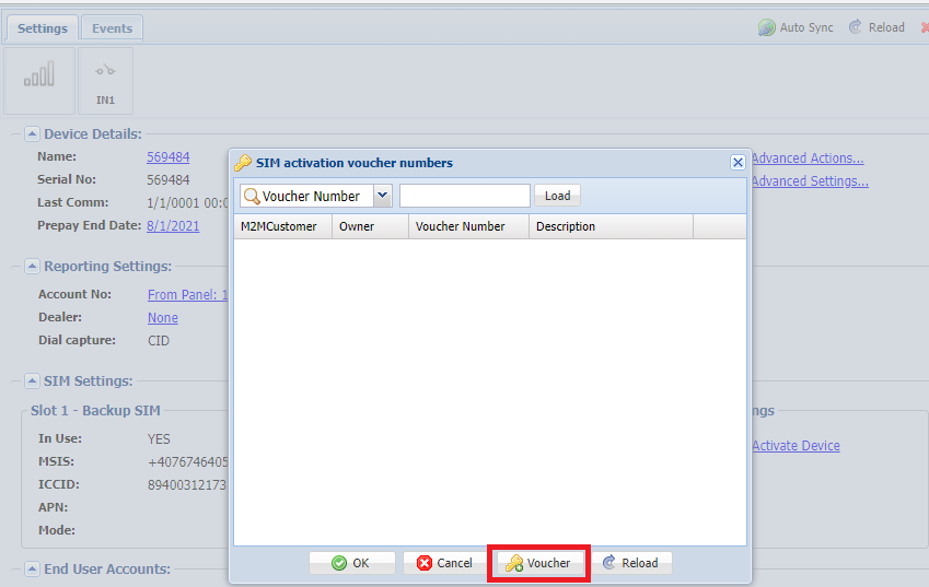
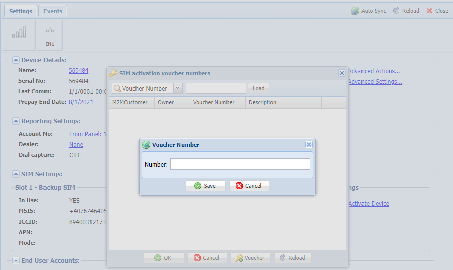
We will then see another option, where we click on “voucher.”

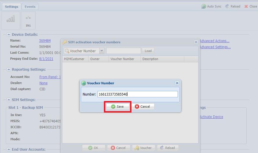
A new window will open where we can enter the REACTIVAM2M voucher code found on the invoice.

In the invoice there will be 15 digits that would be our “Voucher Number” enter those digits

After entering, click save

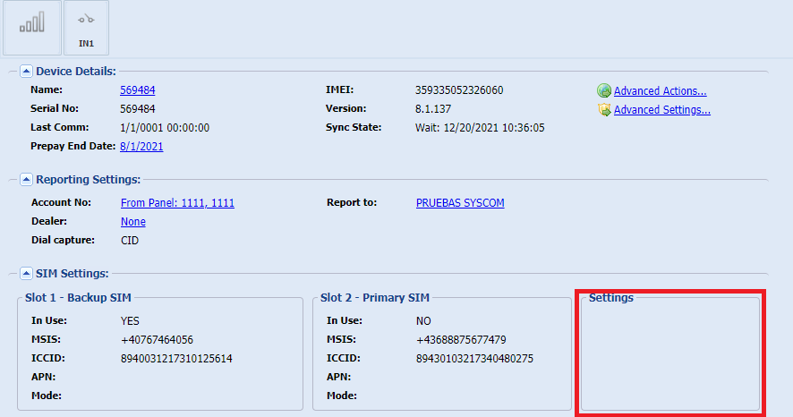
Verify that the option of (ACTIVATE DEVICE) disappears.

NOTE
It is important to enter the annual voucher as soon as possible, as the reactivation code only gives you until the end of the current month to enter the annual payment. If the annual payment is not entered, the communicator will be suspended. In this case, another reactivation code must be purchased to reactivate the communicator.

How to reset a password for epcom devices?

In the following manual, we explain the process to follow so you can reset the password of epcom devices using XML.

To reset the password of an epcom brand IP camera with firmware version 5.3.0 or higher, of a DVR/NVR with firmware version 3.1.7 or higher, or of a video intercom or alarm, it is necessary to carry out the following procedure:

1.- Download and install the software SADP version 3.0.4.9 (download here).

2.- Select the device on which you want to reset the password, press the Forgot Password button (located in the lower right corner), press the “Export” button, and select the folder you want to save the exported file (XML).

3.- Email the previously generated XML file to the following email addresses: [email protected], followed by the following information:

  • Complete serial number in SADP. (Example: DS-72xxABCDXY/SN123456789ABCD123456789ABCD)
  • Full name of the applicant.
  • Customer number and billing name in SYSCOM.
  • Name of the company.
  • Phone number.

You will receive an XML file in response in order to import it. (The response may take approximately 15-20 minutes)

In case you need to reset several devices, please send an email per file with all the information.

It is necessary to send the files without compression, send the file as the software outputs it.

4.- Load the XML file in SADP, set a password of 8 characters (at least one letter and one number), confirm it, and finally press the “Confirm” button so that the password is reset.

Important notes:

  1. The password reset procedure is only valid on the same day.
  2. The device should not be restarted during the entire procedure.
  3. SADP versions 3.0.0.1 or higher support the new procedure, previous ones do not.
  4. The service hours are from 9:00 a.m. to 6:00 p.m. from Monday to Friday (Miami time)
  5. In case you need the file urgently, please contact the Engineering Department.
  6. In case you need to reset several devices, please send an email per file.
  7. If the file does not work for you, please restart the device to be reset, close the software, and run it as an administrator to generate a new file and repeat the sending process (as a recommendation, connect the device directly to your computer, the computer should have a fixed IP)
  8. It is also possible to generate the file through the iVMS-4200 software.

EPCOM PROAUDIO – Connecting Speakers to Amplifier SF-B120 / SF-B240

The high-impedance audio systems help us connect multiple speakers to the same amplifier output and take these speakers to bigger distances.

The EPCOM PROAUDIO amplifiers give us a 120W output on the SF-B120 model and 240W for the SF-B240 model.

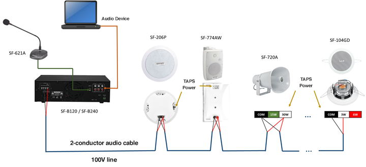
The connection of a Public Address (PA) system with 1 output is done by connecting our speakers in a “daisy chain” making the proper power connection in each speaker (TAPS); having only one line of speakers in our zone.

We can connect a microphone to the PA system and an external audio device to play audio on your system.

The connection diagram would be as shown below:

With this connection, we can operate a PA/ambient music system of 1 zone or output with several speakers playing.

NOTE: It is recommended to only have 80% of the power delivered by the amplifier to power the speakers and leave 20% free to operate safely and without damaging the products.

If you have any questions, please contact the engineering department.