How to get your Low Voltage License in Texas

how to get your low voltage license in texas

If you’re aiming to work on alarm systems, video surveillance systems, or telecommunications networks, obtaining your Texas low voltage certification is a crucial step. This guide will take you through the necessary steps to kickstart your career in the low-voltage industry.

Licensing Overview

In Texas, individuals and businesses engaging in non-exempt electrical work, including low-voltage projects, must be properly licensed. This ensures compliance with state regulations and standards for safety and quality in electrical services. The Texas Department of Licensing and Regulation (TDLR) outlines that anyone performing electrical work, which inherently includes low-voltage work, must hold a valid license. This includes various classifications of licenses, such as Apprentice Electrician, Journeyman Electrician, Master Electrician, and various contractor licenses.

Your Path to Certification

Your journey to becoming a certified low-voltage professional begins once you start working for one of your local security professionals. Here are the essential steps:

  1. Gain Experience Through Apprenticeship: Dive into the real action with an apprenticeship. Think of it as learning by doing. You’ll team up with seasoned professionals who will show you the ropes—from wiring up security systems to setting up smart home tech. It’s all about getting your hands dirty and seeing how things work in the real world.
  2. Work on Various Projects: Grab every chance to work on different projects, maybe as a journeyman, to round out your skills. This mix of learning on the job and tackling various tasks is your golden ticket to becoming an expert in the low-voltage installation world.
  3. Study for Your Private Security Exam: Think of this as your final test, covering everything from installation to safety. With your hands-on experience and some solid study sessions, you’ll be ready. Reviewing your materials, keeping a study schedule, and approaching the exam with confidence is key. Passing this is just a win; it’s your ticket to being a certified low-voltage expert.
  4. Apply for Your License: Gather your documents, fill out your application, and submit to your state’s licensing board. Start at the Texas Online Private Security website. You’ll need to select “Start an Individual License,” then “Unarmed,” and then “Alarm System Installer.” Make sure your personal information matches your ID, and that you have your company’s business license ready before proceeding.
  5. Take the Test: After submitting your application, you will receive a test date and location about three weeks from your application being entered. Prepare thoroughly and go take your test.

Specialized Low Voltage Work

Specific exemptions apply to persons working with class 1, 2, or 3 remote control, signaling, or power-limited circuits, fire alarm circuits, optical fiber cables, or communications circuits, where state licensing as an electrician is not required. However, municipal or regional regulations may impose additional requirements. It’s crucial to note that certain types of work and practitioners are exempt from the state’s licensing requirements, though local regulations may vary.

Renewals and Continuing Education

The TDLR website details the process for applying for a new license or renewing an existing one. License holders are required to engage in continuing education to maintain their licenses and ensure they are up-to-date with the latest standards, technologies, and safety protocols.

Additional Certifications

Keep learning! Additional certifications can open up new doors and opportunities within the low-voltage field. With dedication and the right training, the possibilities are endless.

Resources

For detailed information about applying for a license, renewing a license, and continuing education requirements, visit the TDLR Electricians Program pages:

Conclusion

On behalf of the epcom technical team, we’re excited to see where your skills will take you. Remember, epcom is always here to help. We are your one-stop shop for all your integration needs. Hit that like button and subscribe for more insights, and here’s to your success in the low voltage industry!

How To Connect an Intercom to 2 Monitors Using IVMS-4200

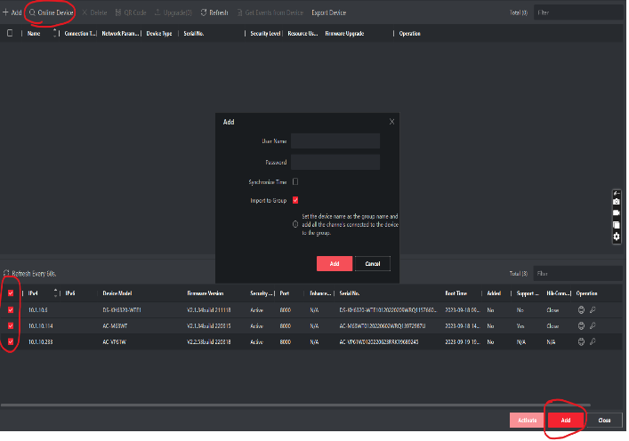
1. First, add your devices to the IVMS 4200 Software, click on “Online
Devices.” Once you see the devices, click on them individually, then click
“Add.”

2. The username is always admin unless you have changed it. Once you fill out
the password, click “Add”

3. Once you have your devices added to the IVMS software

4. To get the serial number of the device on IVMS, click on the configuration
wheel of the “Indoor Station.” Then a menu will pop up

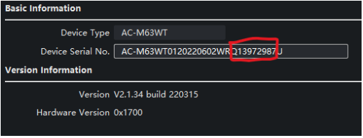
5. Once the menu opens, the first page that will open is “Device Information.”
In device information the last 9 digits before the U is the serial number

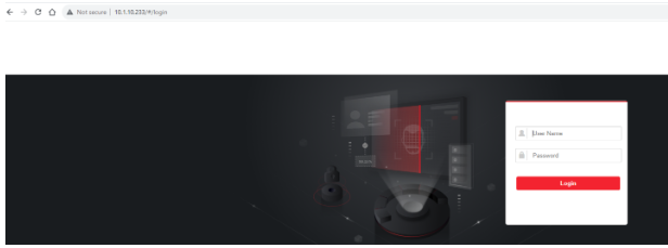
6. Once you have this information, go to your web browser and type in the IP
Address for the Intercom as follows;

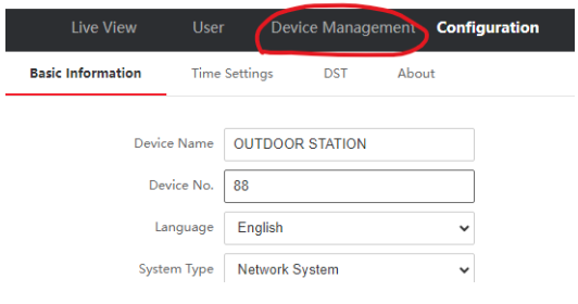
7. Once you login to the intercom, head over to the “Device Management”
tab

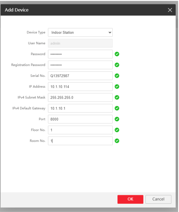
8. Once you are there, go to “+Add”

9. Fill in the fields with the information it asking you

10. Once you fill out the information and click “Ok.” The Registration Password
should be the same as the device password. The device will be added to the
list. It will be listed as Offline until we complete the next step.

11. For the next step, open IVMS-4200 and go to the monitor settings
you just added to the intercom.

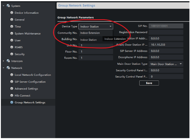
12. A menu will pop up with all the configurations of the Monitor. Once you’re
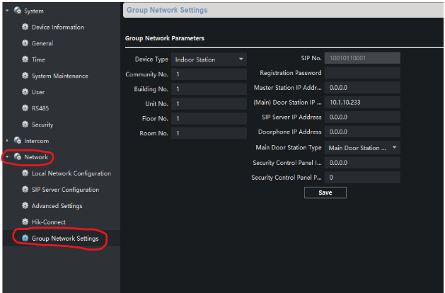
there, go to “Network”, then “Group Network Settings”.

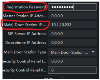
13. Once you are there, in “(Main) Door Station IP” you are going to put in the
IP Address of the Intercom. Once you fill that out, above it says
“Registration Password.” Put the same password you put for the device.
Then click “Save.”

14. Now go back to the “Device Management” page on the intercom, and
verify that under “Network Status” it says Online.

15. Once you have this configured, they should be able to communicate and
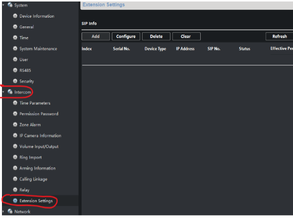
call. To add the second monitor, go to the configuration of the Monitor in
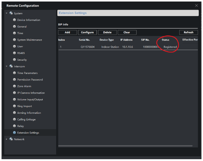
IVMS-4200 and go to “Intercom” and then “Extension Settings.”

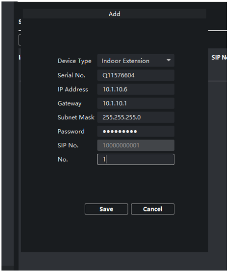
16. Once there, go to “Add.” The information you will fill out here is for the 2 nd
monitor, you will enter the Serial Number of the 2 nd Monitor.

17. Once the information is saved. It will show up on your list as unregistered.
Once it is saved, go to the configuration of the 2 nd monitor. Go to
“Network,” then go to “Group Network Settings.”

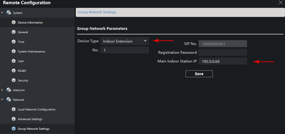
18. Once you change it to “Indoor Extension.” Change the Number to 1. After
you save the configuration the menu will drop down, this will save the
configuration. After that you will open the configuration menu again and go
to “Network,” then “Group Network Settings” again.

19. Once there, Fill in the “Main Indoor Station IP.” This will be the IP address
of the 1st monitor, the Principal Monitor. Along with the registration
password.

20. Once you save the settings, go back to the configurations of the 1st
monitor, the principal monitor. Go to “Intercom,” then “Extension
Settings.” The 2nd monitor should now be registered to the 1st monitor.

21. After this, you have now successfully registered all 3 devices.

Steps to create VLANs with bandwidth limits per user from the Ruijie app

Steps to create VLANs with per-user bandwidth limits using the Ruijie app:

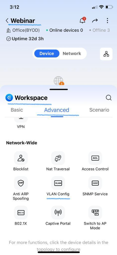
1. Launch the app and make sure you are in the correct Project (In this example, the project is named Webinar).

2. Go to the Workspace / Advanced section. Scroll down until you find the VLAN Config option.

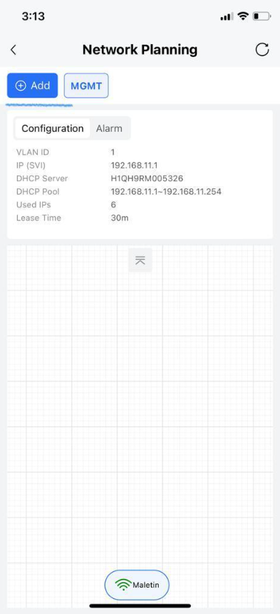
3. Inside VLAN Config, click on the Add button.

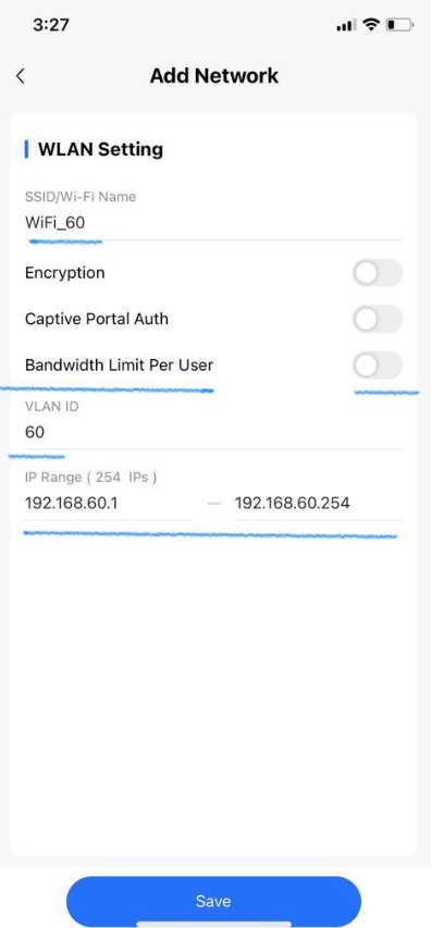
4. Next, name the SSID, specify the VLAN ID, and configure the IP Range, following the image for reference.

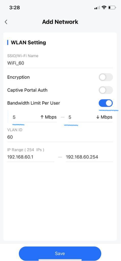
5. To complete the setup, enable the Bandwidth Limit per user option and define the upload and download limits.

6. Click “Save” and your VLAN with per-user bandwidth limits is now configured and ready to use.

8 Safety Solutions by ECCO (made in the USA) – EPCOM Your One Stop Shop

The Evolution of Vehicle Lighting and Safety Systems

In today’s technologically-driven world, the safety and functionality of vehicles have been revolutionized with advanced lighting and camera systems. From construction sites to highways, ensuring optimal visibility and caution is paramount. Let’s delve into some innovative solutions that pave the way for a safer and more efficient future on the roads and beyond.

1. Work Lights

Work lights have transformed the way we operate in low-light conditions. These lights are designed to offer a broader and brighter illumination, making it easier for workers to carry out their tasks efficiently, especially during nighttime or in dim environments.

2. Beacons for All Types of Vehicles

Beacons have become indispensable for various vehicles, from emergency responders to construction vehicles. They act as a warning system, signaling other road users of potential hazards or the need to give way.

3. Mini Light Bars

Mini light bars are compact yet powerful lighting solutions. They’re perfect for vehicles that require intense illumination without the bulk of traditional light bars.

4. Interior Lighting for Vehicles:

Interior lighting goes beyond aesthetics. It plays a pivotal role in ensuring the driver’s comfort, visibility of controls, and overall safety inside the vehicle, especially during nighttime drives.

5. Camera Systems for Vehicles:

With the advent of camera systems, drivers can now have a 360-degree view around their vehicles. These systems are crucial in preventing collisions, assisting in parking, and ensuring the safety of pedestrians and other road users.

6. Backup Alarms:

Backup alarms are a simple yet effective safety measure. They alert pedestrians and other vehicles when a vehicle is reversing, reducing the risk of accidents.

7. Lights for Forklifts / Warehousing applications:

Forklifts operate in tight spaces and often in areas with limited visibility. Specialized lighting for forklifts ensures that operators can see and be seen, ensuring the safety of both the operators and the goods they handle.

8. Directional Lights:

Directional lights guide the way. Whether it’s for turning, merging, or emergency situations, these lights ensure that other road users are aware of a vehicle’s intended movement.


The future of vehicular safety is bright, thanks to these innovative lighting and camera solutions. As technology continues to advance, we can anticipate even more enhanced systems that will further ensure our safety on the roads and at work. Whether you’re a fleet manager, a car enthusiast, or someone concerned about road safety, these advancements are ushering in a new era of vehicular safety and efficiency.

ECCO full portfolio can be found at www.epcom.net contact us at 915-533-5119

EPCOM: EL PASO, SAN ANTONIO, MIAMI

Adding GDS3710 Door Phone to Epcom NVR

Step 1: Prepare the GDS3710 for Connection

  1. Connect to the GDS3710 through a web browser using the default IP address, 192.168.1.168.
  2. Log in with the following credentials:
    • Username: admin
    • Password: The password should be printed on the device.
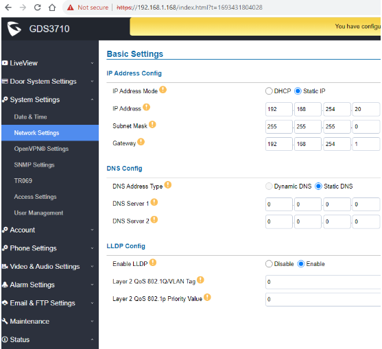
  3. Once inside the GDS3710’s graphical interface, navigate to the “System Settings” menu and select “Network Settings.”
  4. Assign a static IP address to the GDS3710 within the network segment provided by the NVR. This ensures that the camera and the NVR are on the same network. Save the configuration.

Step 2: Configure the NVR

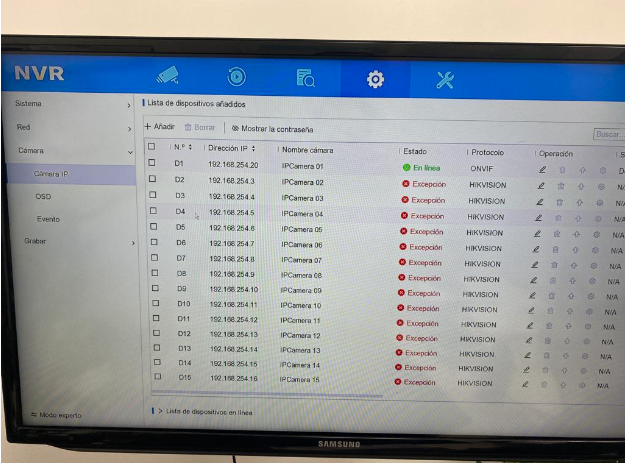
  1. Access the NVR’s graphical interface. You can do this through the NVR’s IP address or by connecting a monitor to the NVR via the HDMI port.
  2. Navigate to the NVR’s settings menu, typically represented by a gear icon.
  3. Then, select “Camera IP” or a similar option in the NVR’s menu.
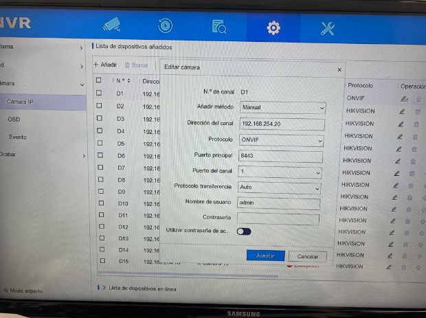
  4. Click the “Edit” button (usually resembling a pencil) on one of the available channels where you want to add the GDS3710 camera.
  5. Select the addition method as “Manual.”
  6. Enter the IP address you configured on the GDS3710 in the corresponding field.
  7. Choose the “ONVIF” protocol (ensure that the GDS3710 camera is ONVIF-compatible) and provide the password you set on the GDS3710.
  8. Save the configuration.

Step 3: Review the Result

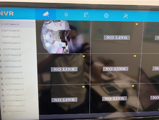
Once you have completed these steps, the GDS3710 should be registered on the NVR as an additional camera. You can verify this by accessing the live view on the NVR and selecting the channel where you added the GDS3710 camera. You should be able to view the camera’s video feed on the NVR.
Ensure that the IP address and password are correct, and both devices are on the same network for the configuration to work correctly.

Hikvision/Video Intercom – Configuring a Door Station for 2nd Generation IP Monitors via IVMS4200

In this technical guide, we will explain the configuration of two monitors and a door station from the new generation of Hikvision video intercom systems.
Before beginning, it’s important to verify and/or perform the following steps:

  1. Ensure all devices, including the computer, are connected to the same network (within the same network segment).
  2. Update both the door station and the monitors to the latest firmware version.
  3. Activate and add the devices to IVMS 4200 version V3.1.1.13 and confirm that they are online.

Note: Updates and software can be downloaded from our portal https://www.epcom.net. Once the devices are updated, it’s necessary to restore them to factory settings to apply the firmware update values.

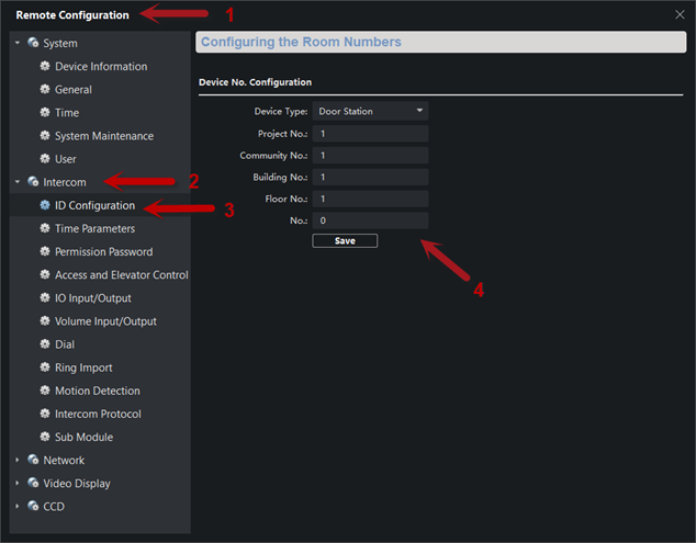
Step 1: Access Remote Configuration (1) on the door station DSK-D8003-IME1 –> Intercom (2) –> ID Configuration (3). Verify that the parameters are set as follows (4).

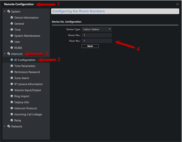
Step 2: Access Remote Configuration (1) on the monitor DSKH-6320-WTE1 –> Intercom (2) –> ID Configuration (3). Under Device Type, select “Indoor Station.” Assign the room and floor numbers; for example, set both as 1 (4).

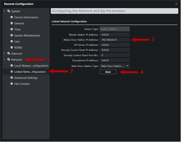
Step 3: Next, in the Network tab (1), select Linked Network Configuration (2). In the (Main) Door Station IP Address (3) field, enter the IP address of the door station. Save the changes (4).

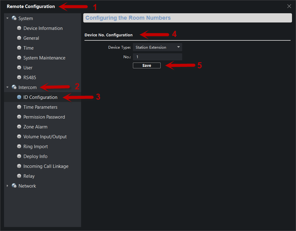
Step 4: Access Remote Configuration (1) of the second monitor DSKH-6320-WTE1 –> Intercom (2) –> ID Configuration (3) –> Device No. Configuration. Select the Station Extension tab and assign the extension number (4). Click Save.

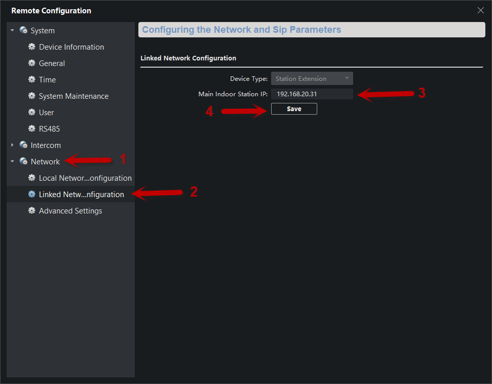
Step 5: In the Network tab (1), choose Linked Network Configuration (2). In the Main Door Station IP Address field, assign the IP address of the main monitor (3). Save the changes (4).

With these simple steps, the video intercom system can make calls to both monitors.

Video Door Entry Systems – Linking 2 or More IP Door Stations

We will outline the basic setup for adding a second (or more) door station to an existing IP door entry system.

We assume the initial system configuration has already been completed (a monitor is already set up with the main door station). Now, the next step is to link the additional missing door stations.

To begin, it’s important to identify our devices, as shown in our IVMS4200 program.

In this example, we already have an additional monitor, which does not affect our configuration.

The key concept to understand for performing this setup is as follows:

  • There are 2 passwords:
    1. Password: The activation password for the devices (the usual one)
    2. Registration Password: The key that allows the secondary door station to register with the main door station (i.e., to link them).

SETTINGS ON THE SECONDARY DOOR STATION

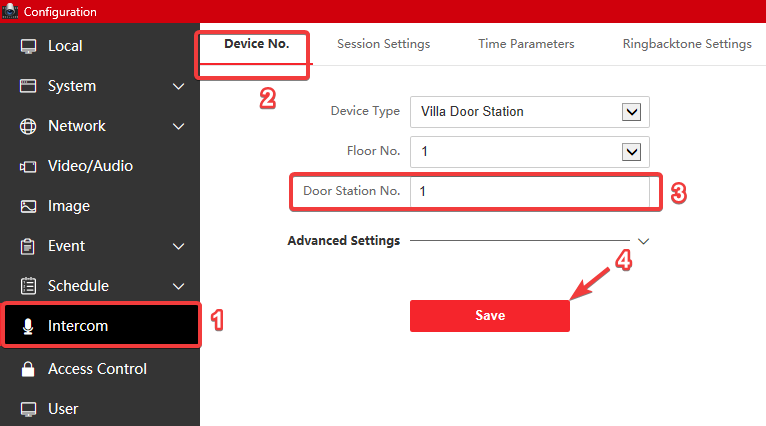
To begin, access the configuration of the SECONDARY DOOR STATION and set it as a slave (replace the number 0 with the number 1 if it’s the first slave station, number 2 if it’s the second, and so on). Do this in the “Villa Door Station No” parameter within the menu located below:

  • After that, the door station will restart.

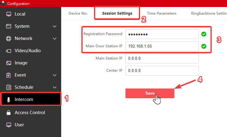
Once rebooted, navigate to the “Session Settings” menu and enter the following:

  1. Main Door Station IP: Enter the IP address of the main door station.
  2. Registration Password: Here, you can assign any password you prefer. For our example, we’ll use “12345abc”.

Note: It’s preferable to use the same password as the activation password of the door station.

SETTINGS ON THE MAIN DOOR STATION

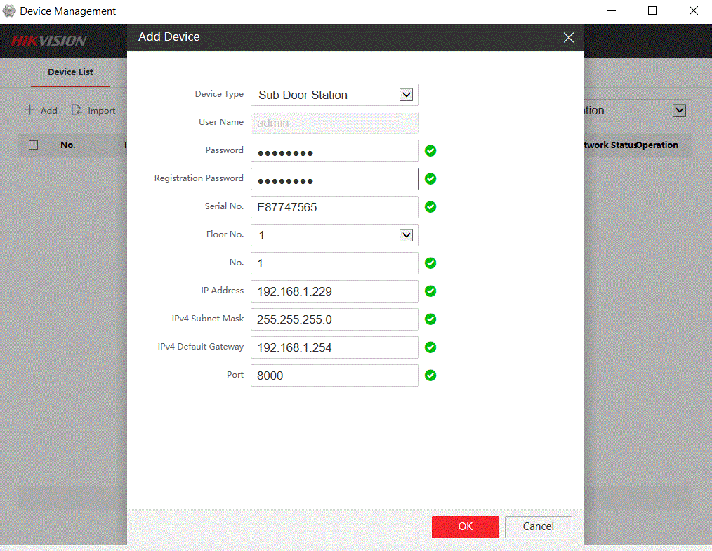
It’s necessary to access our main door station, select “Device Management,” and add the details of our secondary door station.

*NOTE: If your door station is DSKD8003IME1, then you must use remote configuration through IVMS4200. If your door station is a different model, you can do it through its web interface.

The information you input must be accurate for the secondary door station. Once you’ve entered the details, click “OK” (save). After about 1 minute, your second door station will be successfully added without any issues.

3 Undeniable Advantages of RUIJIE as a Leading Connectivity Solution

Now more than ever, it is essential for any company to have a reliable connectivity system. For this reason, we have compiled the reasons why system engineers endorse migrating to RUIJIE in their installations:

1. No need for a controller: RUIJIE is a network solution that does not require a centralized controller for its operation. This means you don’t have to invest in an additional device or worry about configuring and managing a controller. You can simplify your network infrastructure and reduce associated costs by eliminating this additional layer.

2. Unlimited device capacity in the cloud: RUIJIE offers unlimited device capacity in its cloud, which means you can connect and manage many devices in your network without restrictions. This greatly benefits growing organizations or enterprise environments where the number of connected devices can increase rapidly. With RUIJIE, you won’t have to worry about reaching capacity limits and can scale your network according to your needs.

3. Network configuration in 3 minutes: RUIJIE stands out for its user-friendliness and the speed at which a network can be configured. You can set up your network in just 3 minutes, whether it’s 10, 20, 100, or 1000 devices. This saves time and effort compared to more complex solutions requiring lengthy and complicated configurations.

Remember that when considering a change in your network infrastructure, it is important to carefully assess your specific needs and conduct tests to ensure the proposed solution is compatible with your technical and operational requirements.

For quotations and more information, contact [email protected] or visit www.epcom.net.

How to enable audio via Coax. on an EV4016TURBOGEN3 DVR

In this post, we are going to explore how to enable camera audio on your DVR via coaxial cable. This configuration can only be done locally on the DVR this option is not available online.

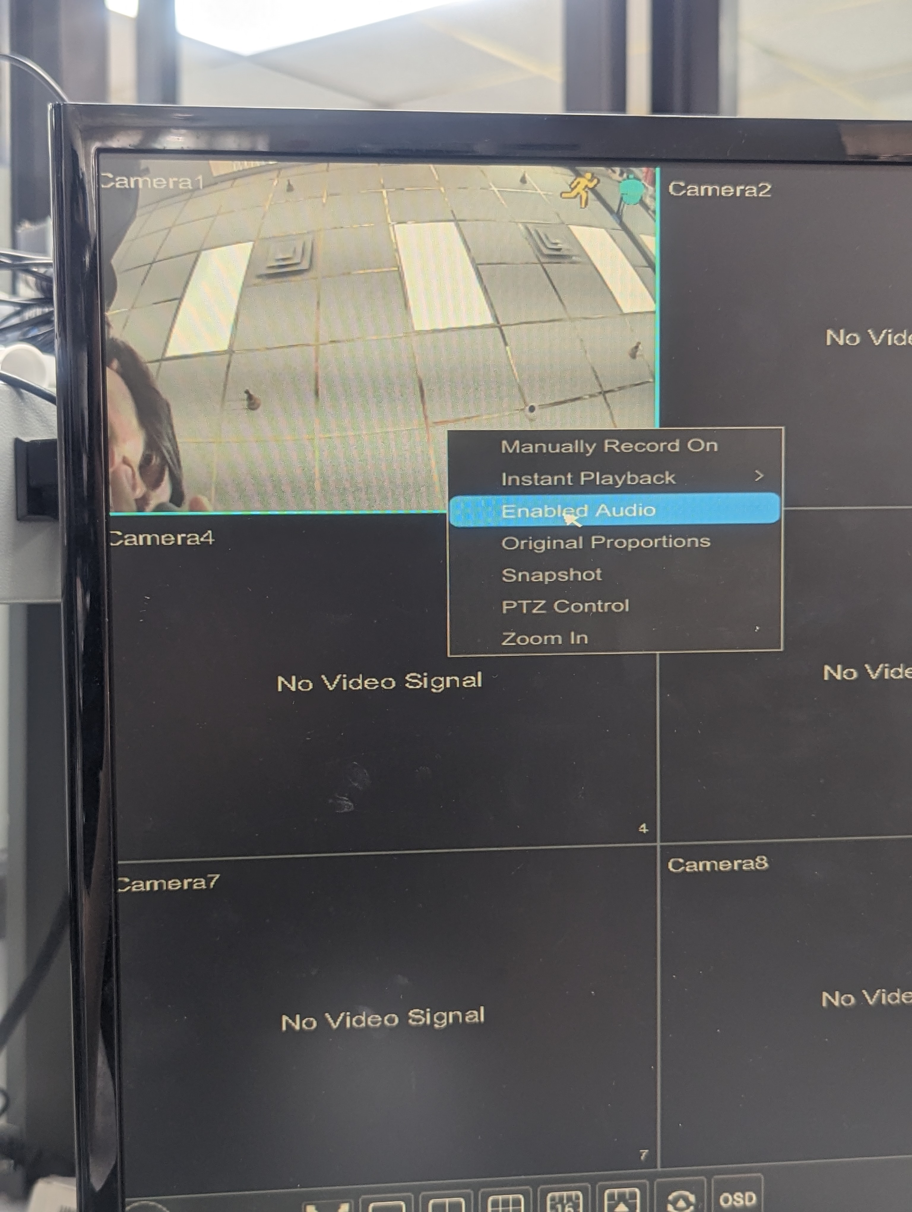
Step 1: Ensure that your camera has the option for “Enabled Audio”.

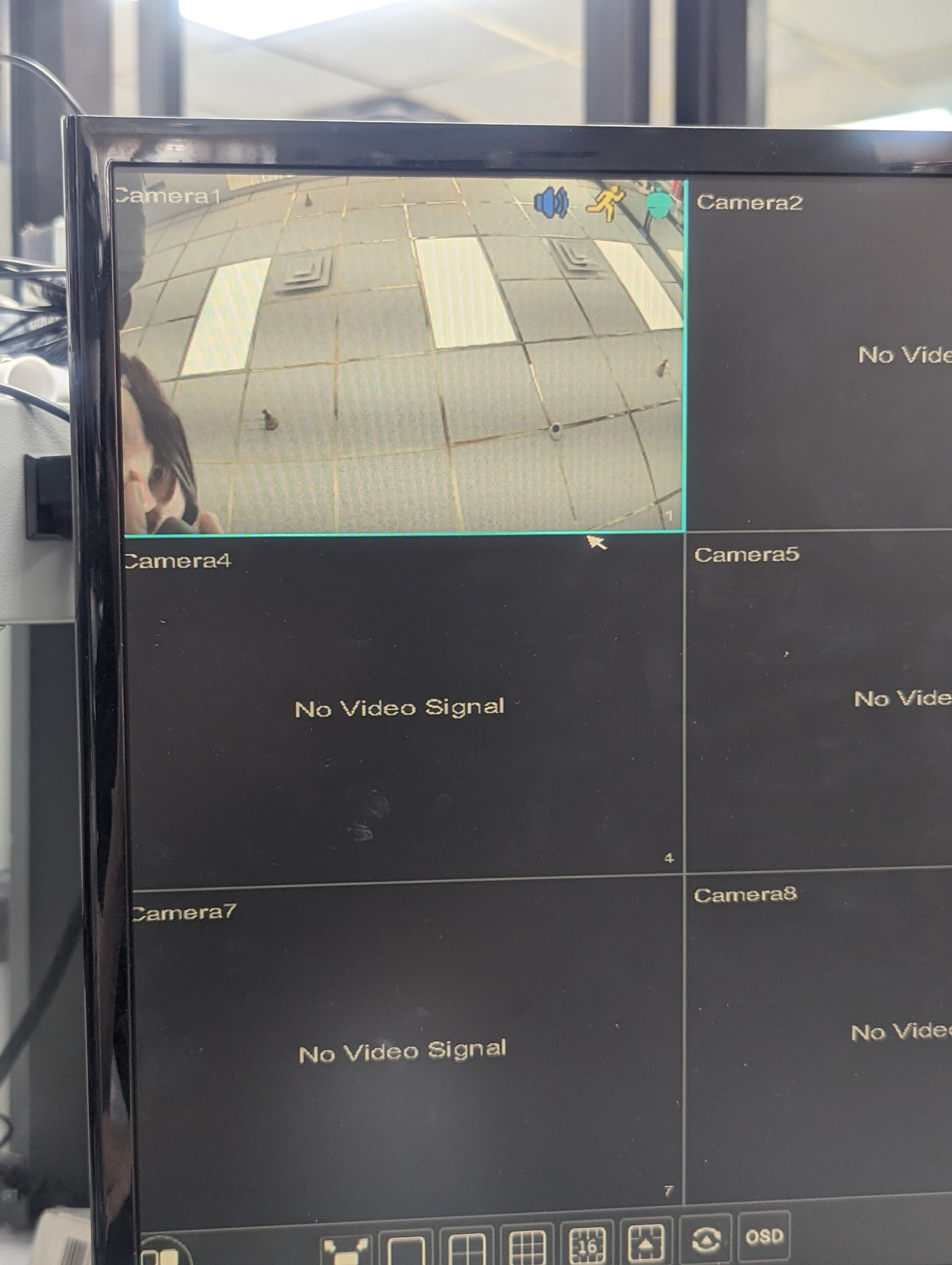
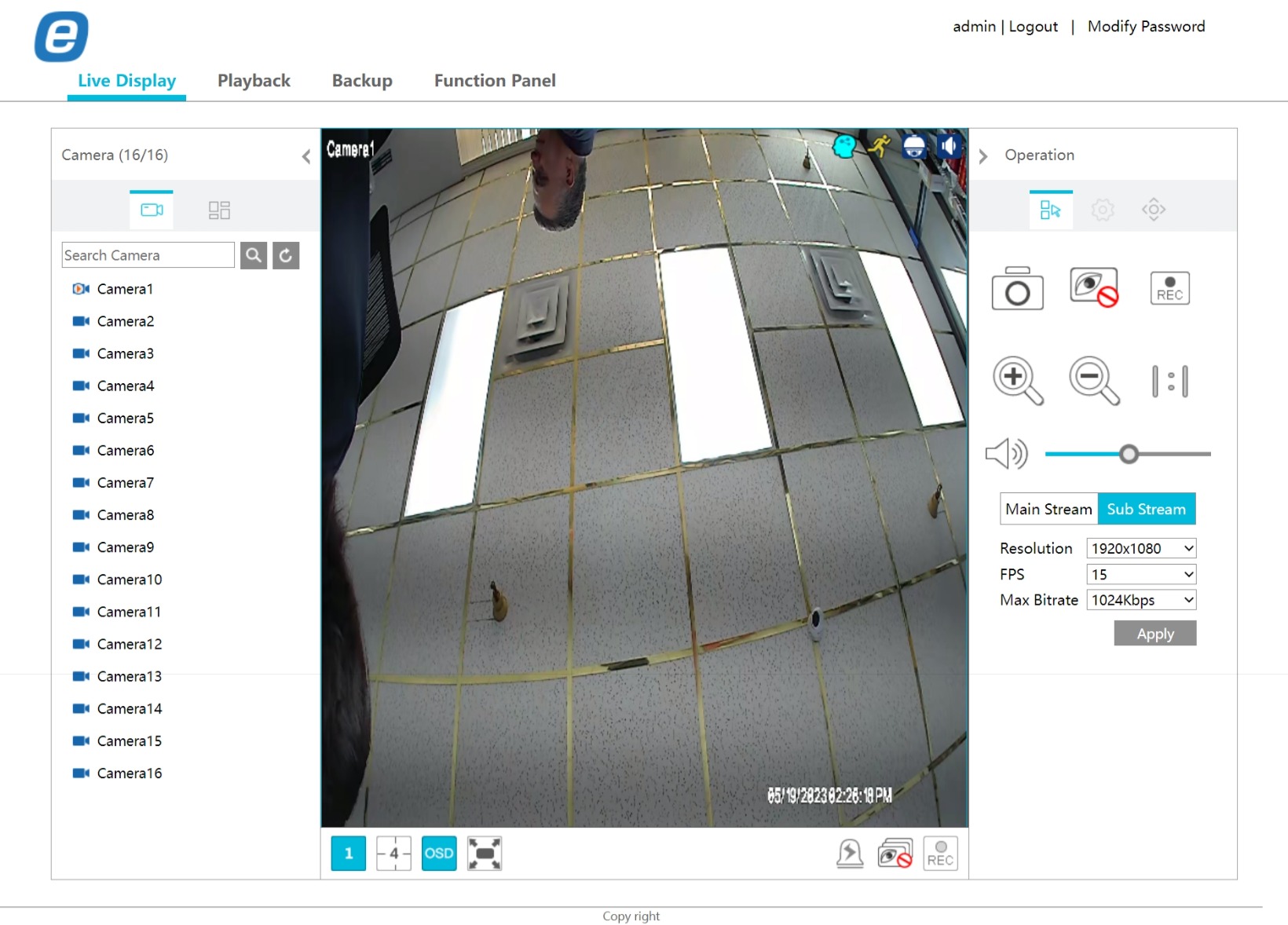
If the audio is enabled, you can see the blue speaker icon appear.

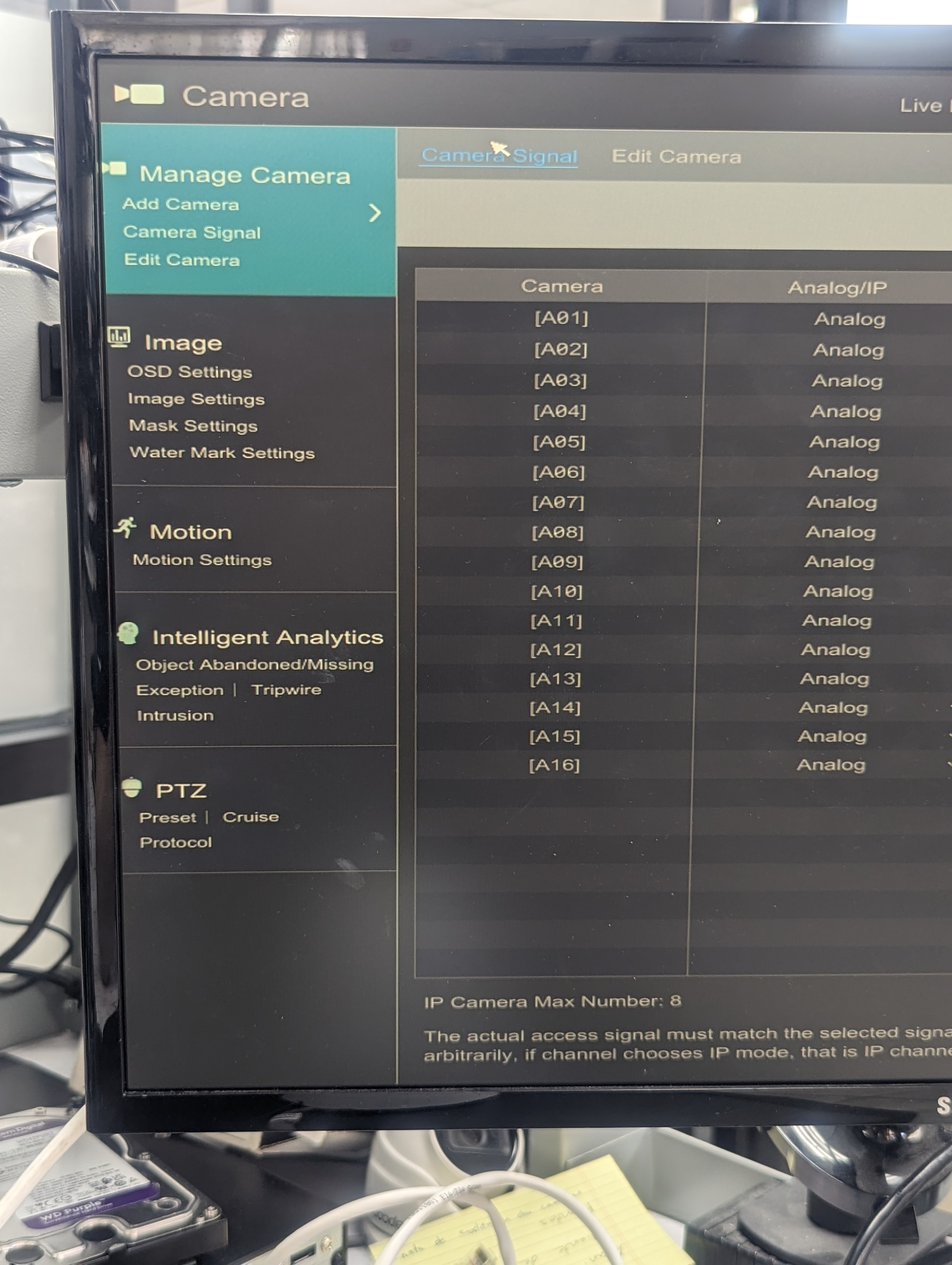
Step 2: Go to the camera section and click on camera signal

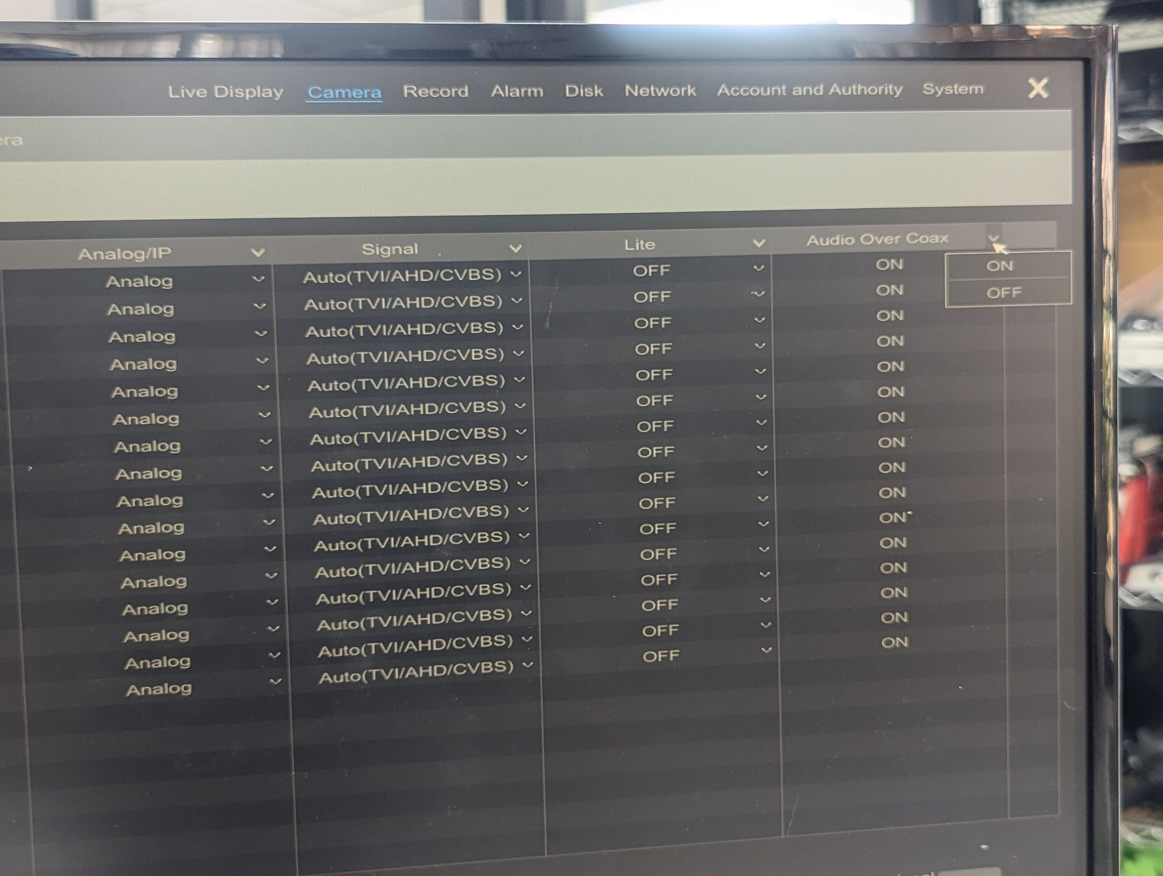
Step 3: Once in camera signal ensure Audio over Coax is ON, you can configure this option by clicking on the arrow.

Step 4: Viewing the camera online on Live Display make sure the volume is activated, you should be able to listen to the audio. With this your audio configuration is done.

Note: Two-way audio is only possible in IP devices.

ACM63WT Display and ACVP61W Door-Phone: A Comprehensive Connection Guide

Welcome to the connection guide for the ACM63WT displays and ACVP61W door-phone. This guide will walk you through the process of connecting these devices using a PoE switch connection. By following the steps outlined in this guide, you will be able to activate your ACM63WT displays and ACVP61W door-phone and visualize them on the IVMS-4200 software.

Please note that this guide assumes that you have access to a PoE switch and that your devices have already been given IP addresses on the same IP segment.

With that said, let’s get started and connect your ACM63WT displays and ACVP61W door-phone to your network for optimal performance.

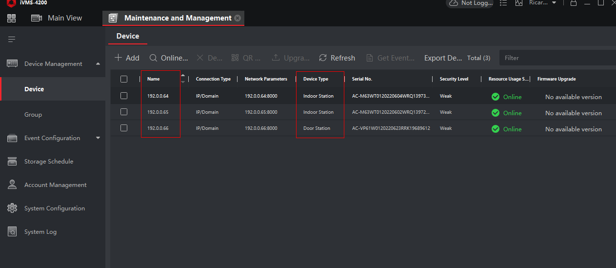
IVMS-4200 activated devices

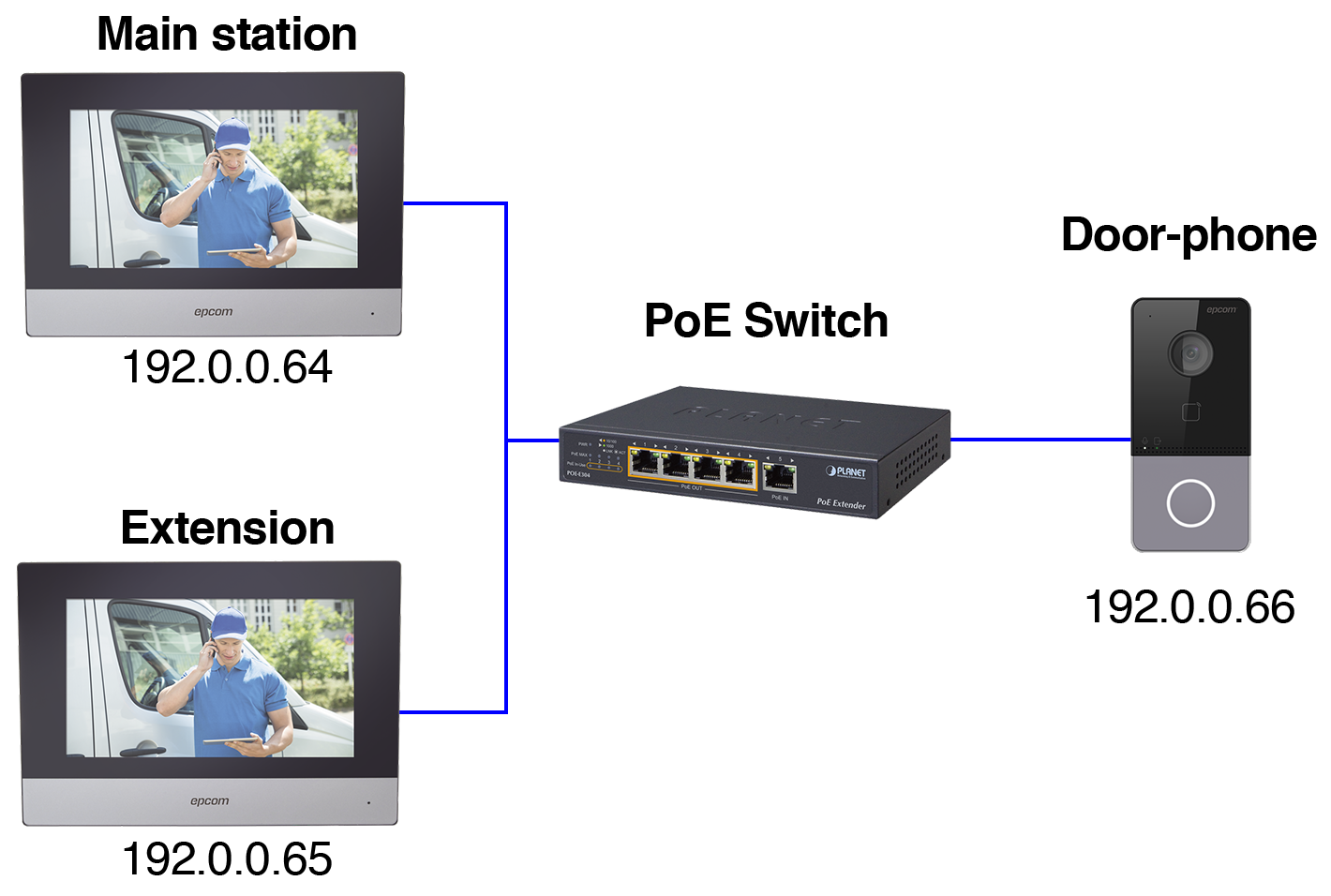
Here is a connection diagram showing the IP addresses of the devices to help you visualize how they are connected to the network.

Device connection diagram with PoE.
  • Main station display: 192.0.0.64
  • Extension display: 192.0.0.65
  • Video door-phone: 192.0.0.66

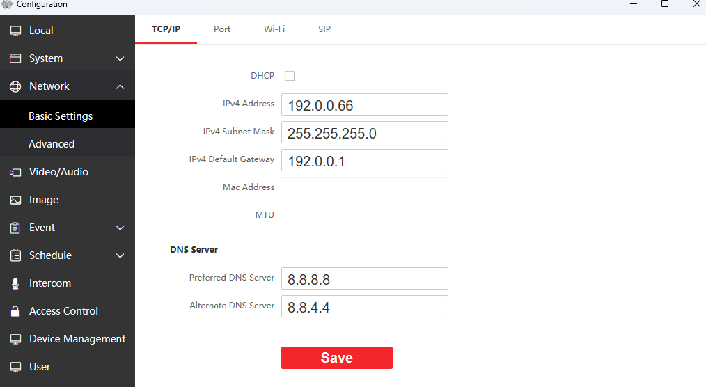
This is the configuration of our video door-phone. We are checking our IP address (192.0.0.66) we will have to check on the main indoor station that they match.

Basic settings, video door-phone IP network settings in the image, the MAC address, and MTU have been hidden.

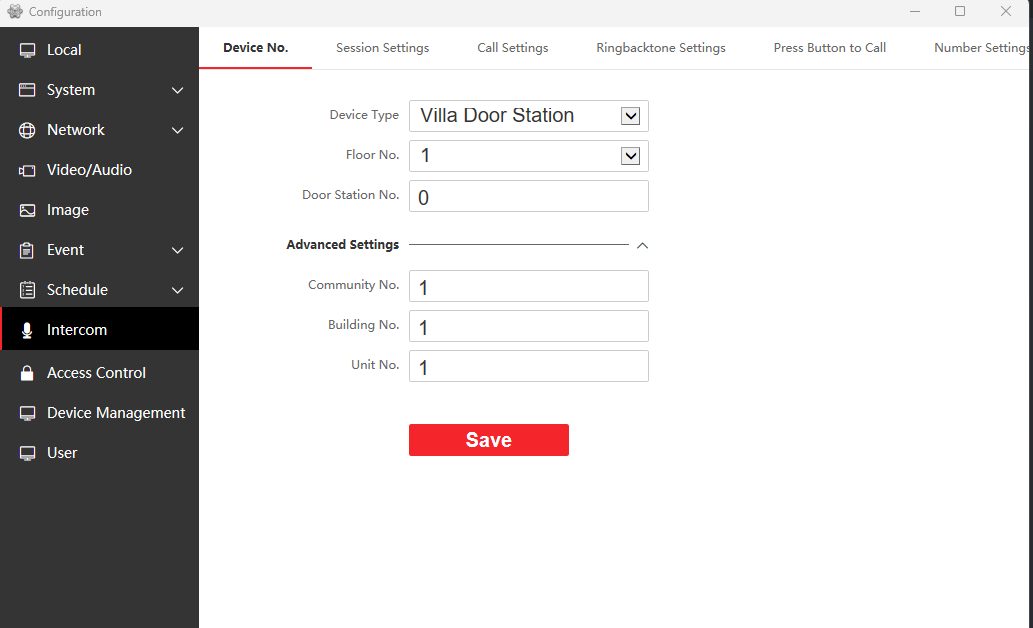
Check that the settings are the same on the intercom tab.

Video door-phone intercom settings

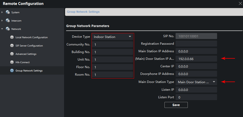
These are the settings for our main indoor station; check that the settings on the red box are the same.

Check that (Main) Door Station IP Address matches your door-phone IP address (in this example, 192.0.0.66). Also that your Main Door Station Type matches the option shown in the image.

Group network settings for the main indoor station

Check the settings of your ACM63WT extension, that Device Type matches Indoor extension and that Main Indoor Station IP matches your main ACM63WT IP address (192.0.0.64).

Group network settings for the indoor extension