Cómo conectar un intercomunicador a 2 monitores utilizando IVMS-4200

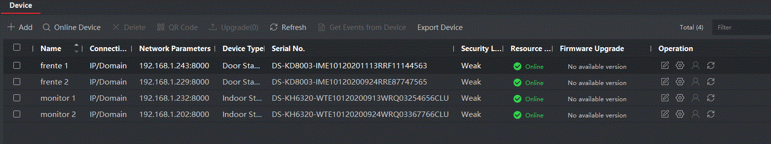
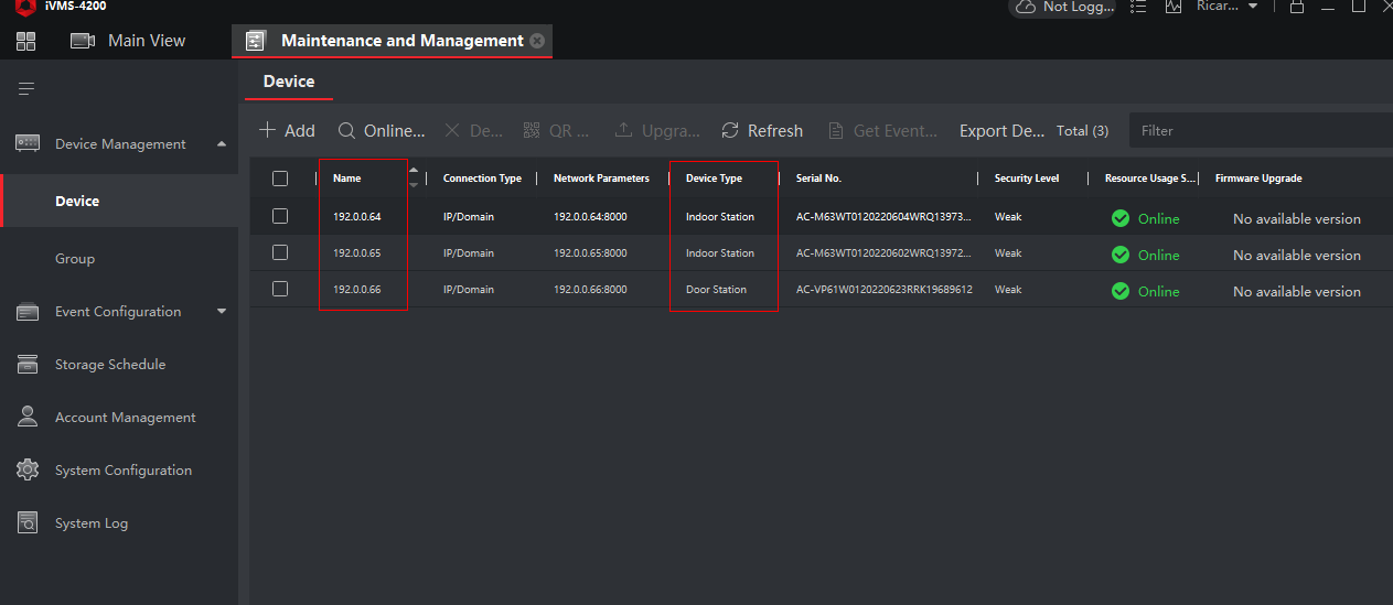
1. Primero, agregue sus dispositivos al software IVMS 4200, haga clic en “Online Devices”. Una vez que vea los dispositivos, haga clic en cada uno de ellos y luego en “Add”.

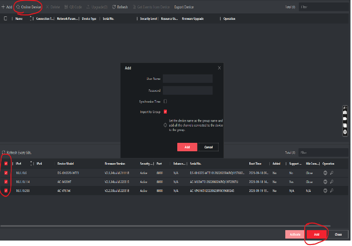
2. El nombre de usuario es siempre “admin” a menos que lo haya cambiado. Una vez que complete la contraseña, haga clic en “Agregar”.

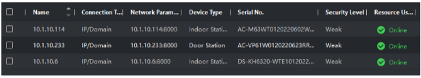
3. Una vez que haya agregado sus dispositivos al software IVMS.

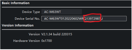
4. Para obtener el número de serie del dispositivo en IVMS, haga clic en la rueda de configuración de la “Indoor Station”. Luego aparecerá un menú.

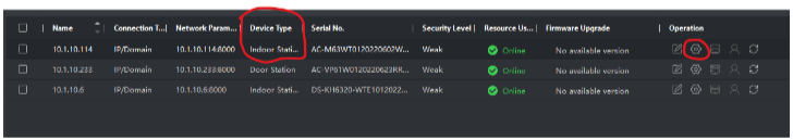
5. Una vez que se abra el menú, la primera página que verá es “Información del dispositivo”. En la información del dispositivo, los últimos 9 dígitos antes de la letra “U” son el número de serie.

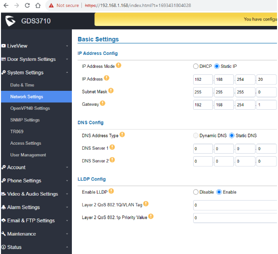
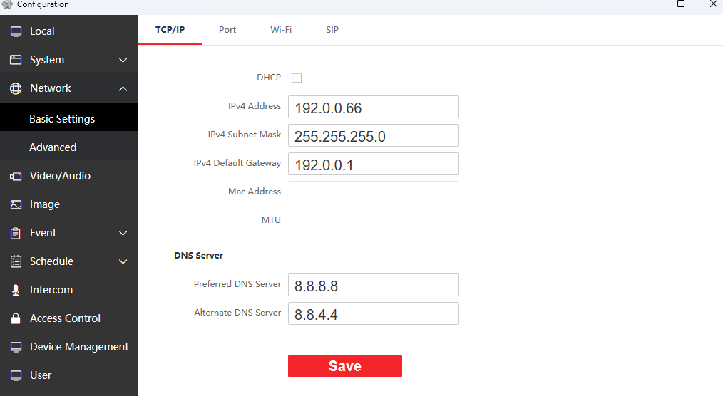
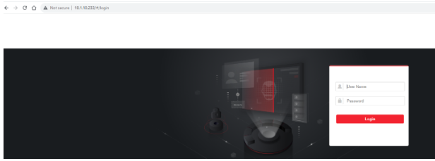
6. Una vez que tenga esta información, vaya a su navegador web e ingrese la dirección IP del intercomunicador de la siguiente manera:

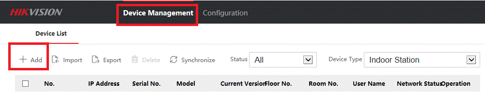
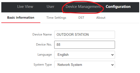
7. Una vez que haya iniciado sesión en el intercomunicador, diríjase a la pestaña “Device Management”.

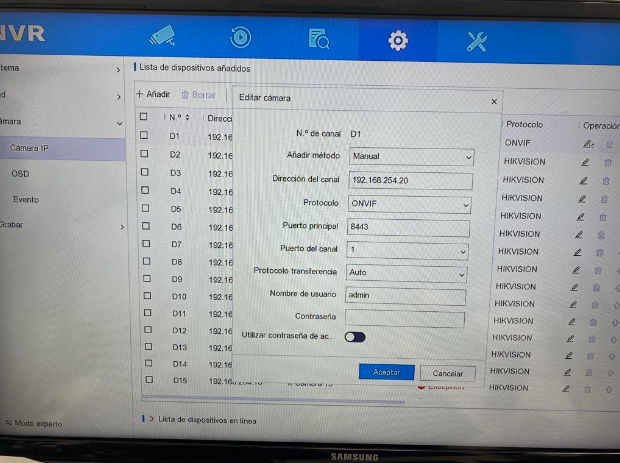
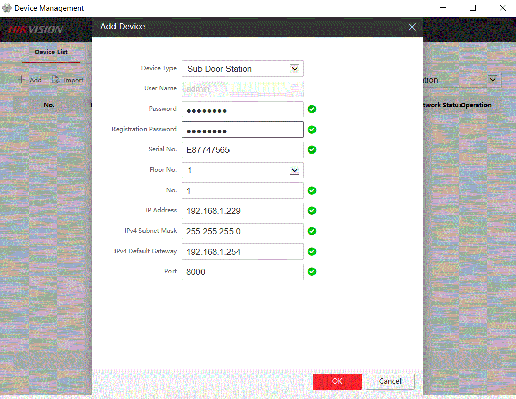
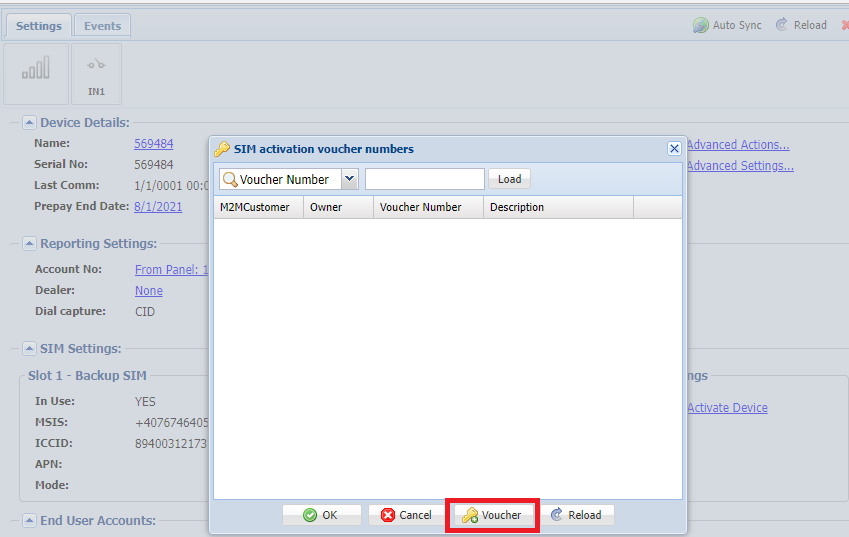
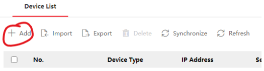
8. Una vez allí, haga clic en “+Add”.

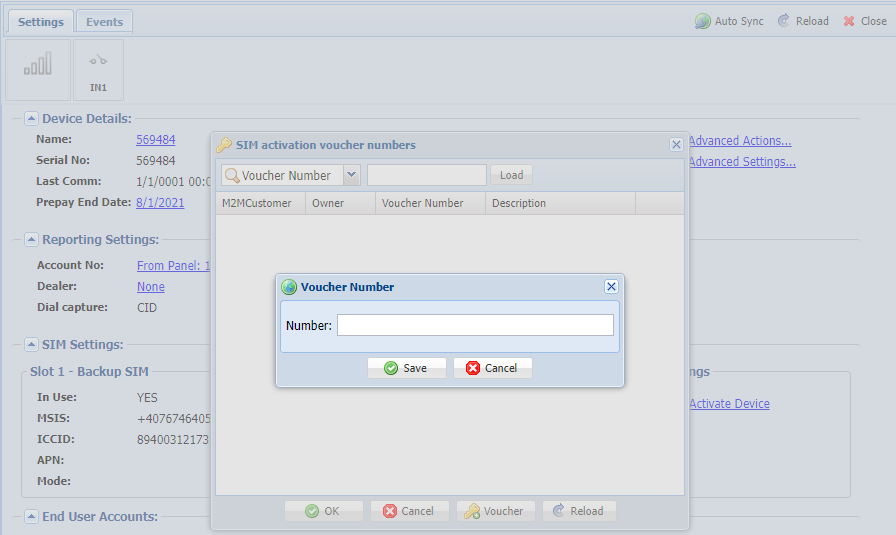
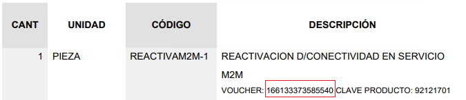
9. Llene los campos con la información que le solicita.

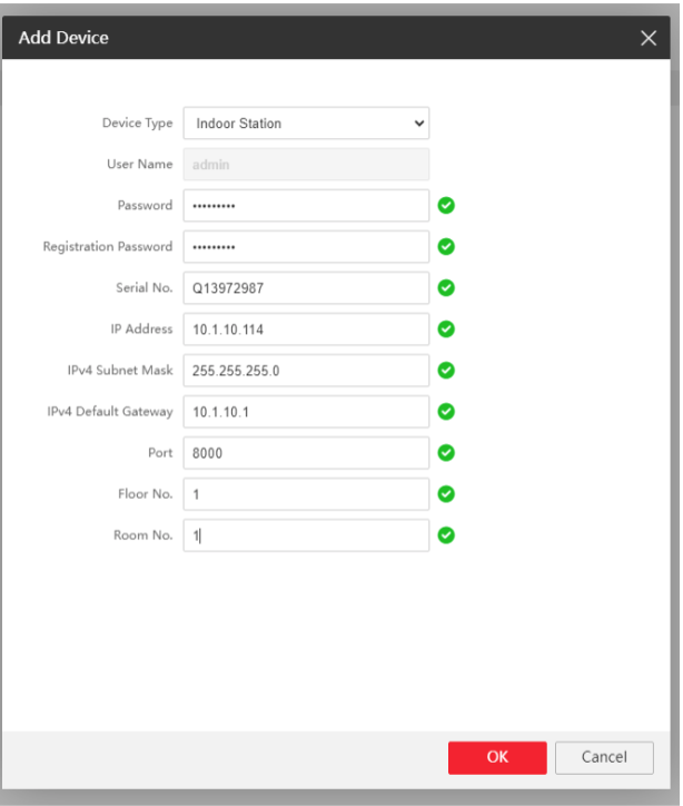
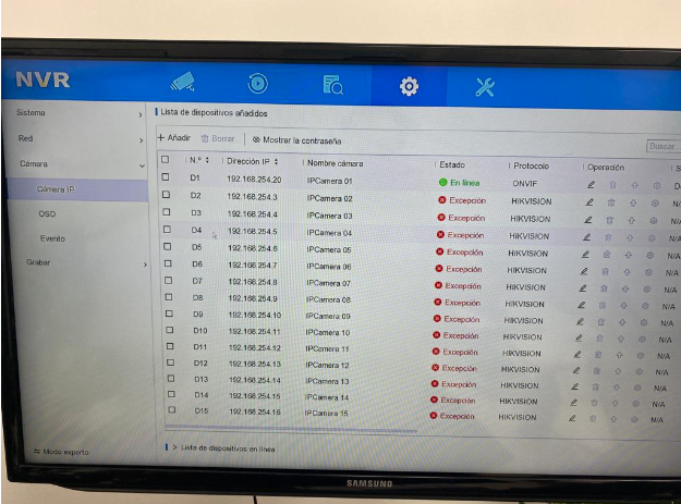
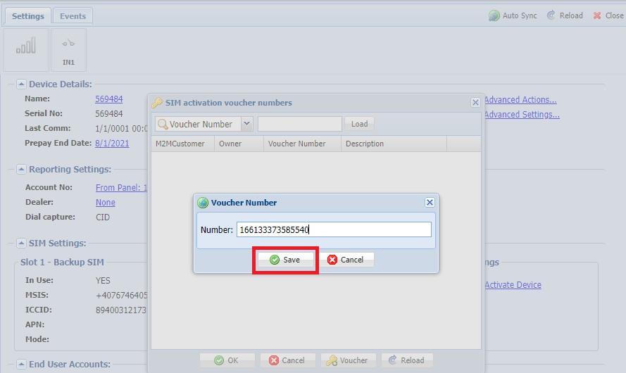
10. Una vez que complete la información y haga clic en “Ok”, la contraseña de registro debe ser la misma que la contraseña del dispositivo. El dispositivo se agregará a la lista. Aparecerá como “Offline” hasta que completemos el siguiente paso.

11. Para el siguiente paso, abra IVMS-4200 y vaya a la configuración del monitor que acaba de agregar al intercomunicador.

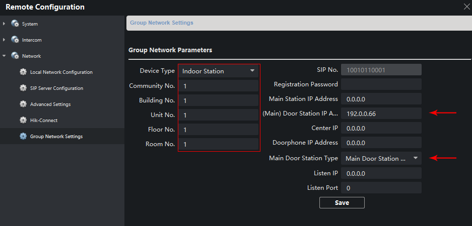
12. Aparecerá un menú con todas las configuraciones del monitor. Una vez allí, vaya a “Network” y luego a “Group Network Settings”.

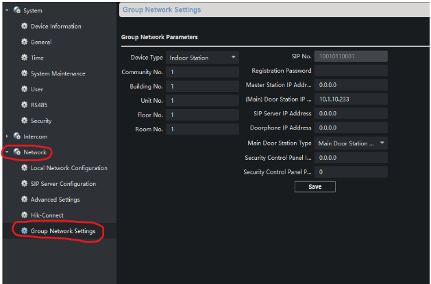
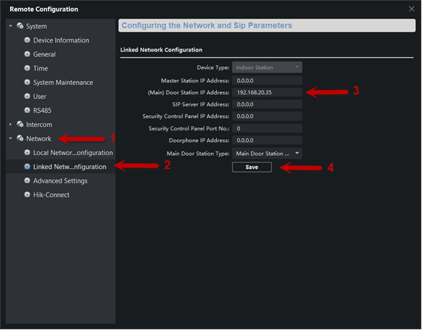
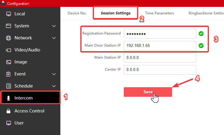
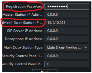
13. Una vez allí, en “(Main) Door Station IP”, debe ingresar la dirección IP del intercomunicador. Una vez que complete eso, arriba dice “Registration Password”. Coloque la misma contraseña que ingresó para el dispositivo. Luego haga clic en “Save”.

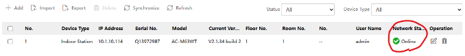
14. Ahora regrese a la página de “Gestión de dispositivos” en el intercomunicador y verifique que bajo “Estado de la red” diga “En línea”.

15. Una vez que tenga esto configurado, deberían poder comunicarse y llamar. Para agregar el segundo monitor, vaya a la configuración del monitor en IVMS-4200 y vaya a “Intercom” y luego “Extension Settings”.

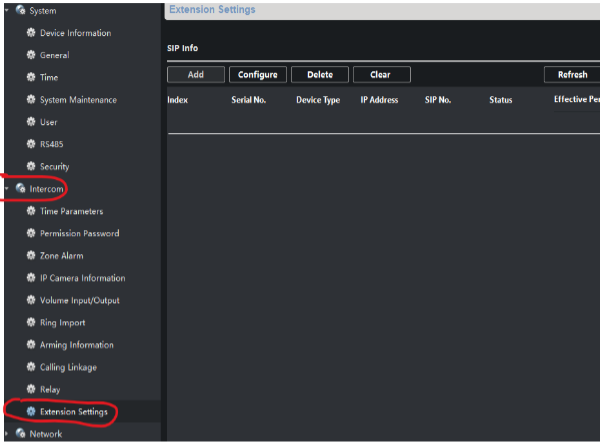
16. Una vez allí, vaya a “Add”. La información que completará aquí es para el segundo monitor; ingresará el número de serie del segundo monitor.

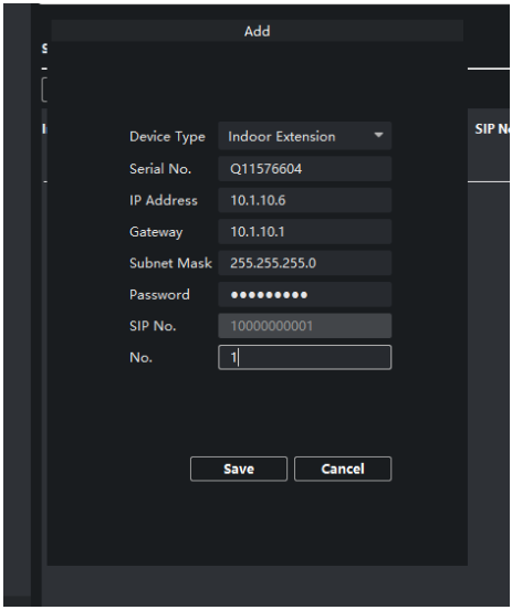
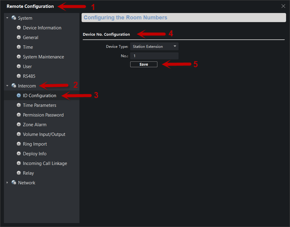
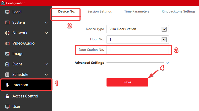
17. Una vez que la información esté guardada, aparecerá en su lista como no registrado. Una vez que esté guardado, vaya a la configuración del segundo monitor. Vaya a “Red” y luego a “Configuración de red de grupo”.

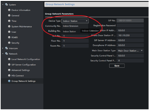
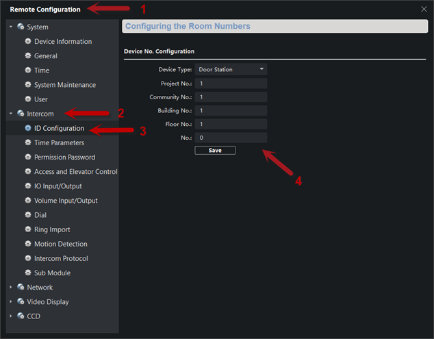
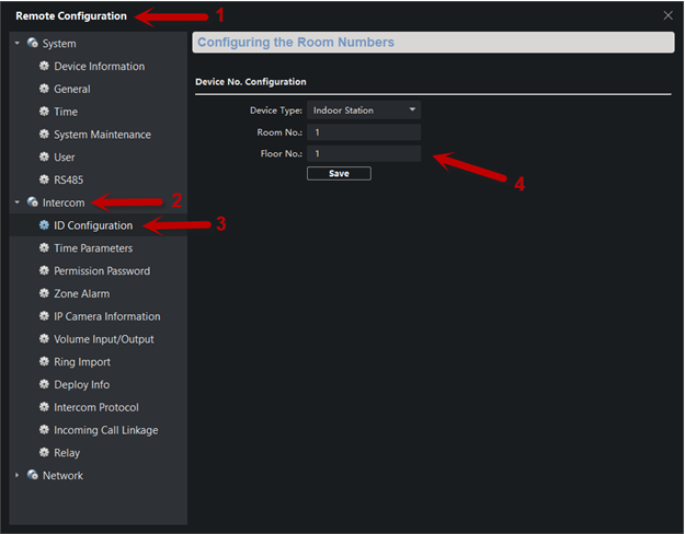
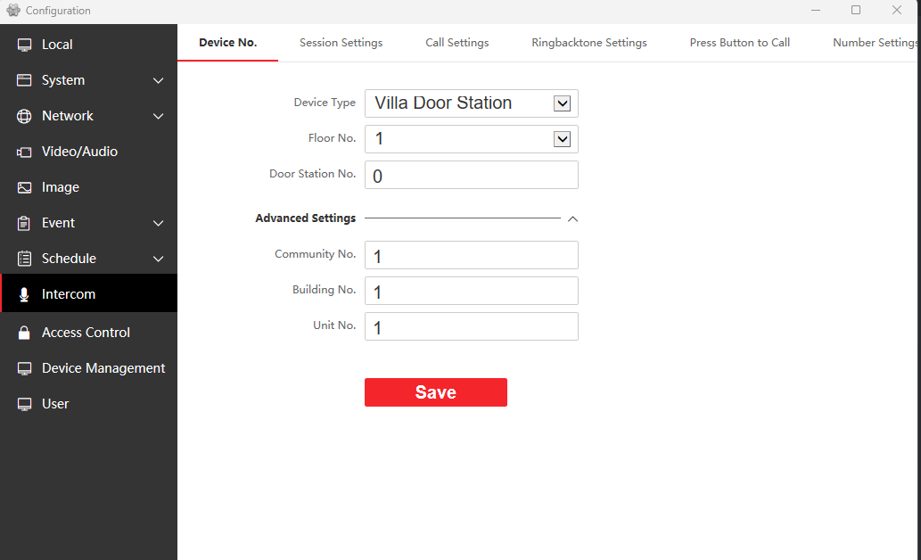
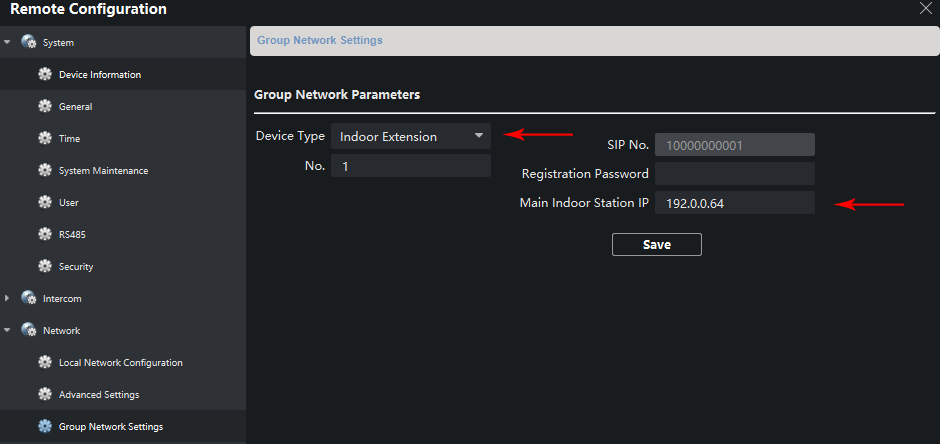
18. Una vez que lo cambie a “Indoor Station”, cambie el número a 1. Después de guardar la configuración, el menú se desplegará, lo que guardará la configuración. Después de eso, abrirá nuevamente el menú de configuración y seleccionará “Network”, luego “Group Network Settings”.

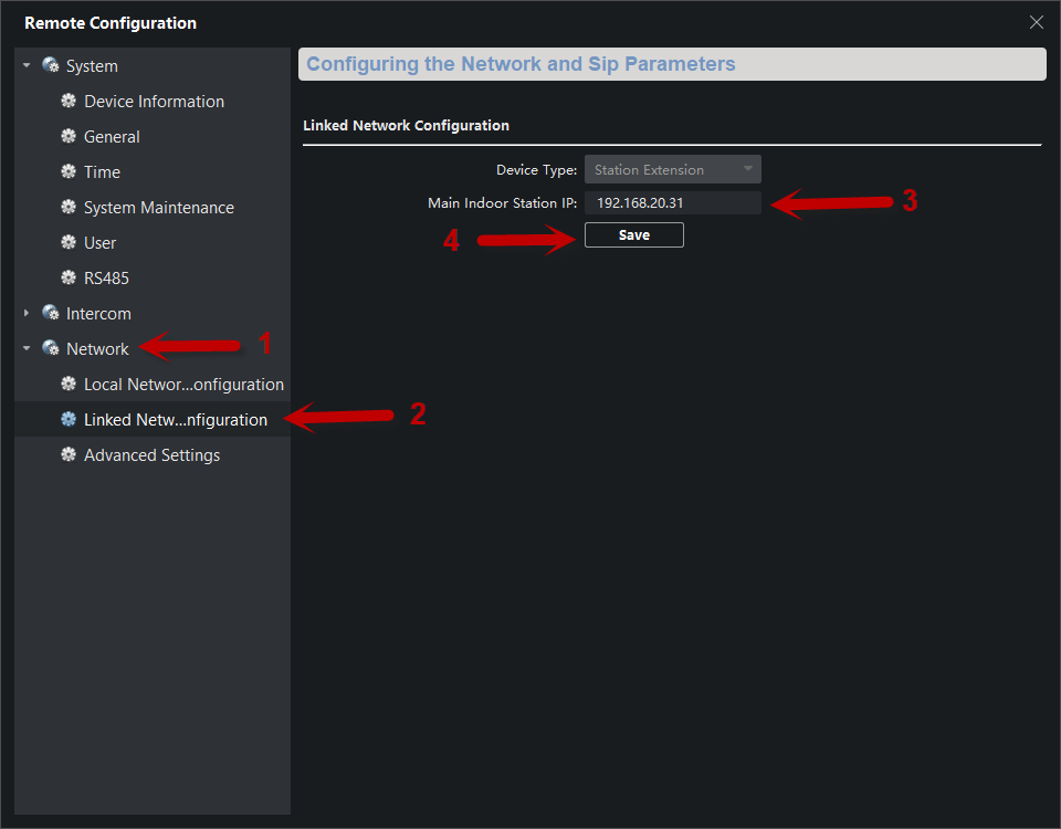
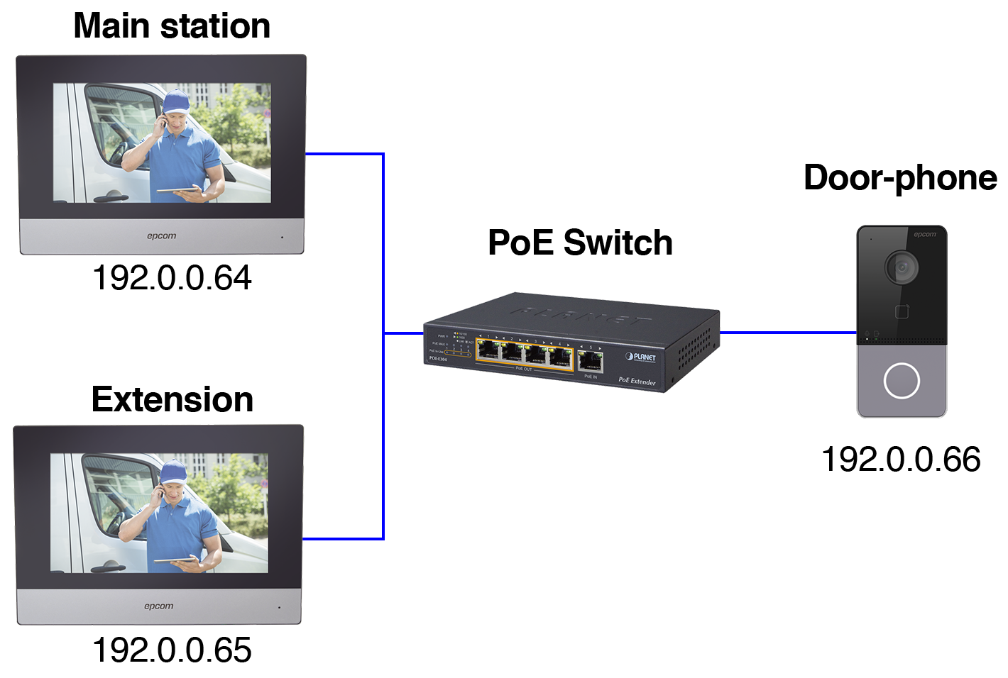
19. Una vez allí, complete la “(Main) Station IP Address”. Esta será la dirección IP del primer monitor, el Monitor Principal. Junto con la contraseña de registro.

20. Una vez que haya guardado la configuración, regrese a la configuración del primer monitor, el monitor principal. Vaya a “Intercom” y luego “Extension Settings”. El segundo monitor debería estar registrado ahora en el primer monitor.

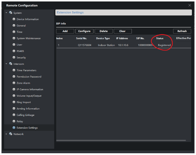
21. Con esto ya registro de manera exitosa los 3 dispositivos

How To Connect an Intercom to 2 Monitors Using IVMS-4200

1. First, add your devices to the IVMS 4200 Software, click on “Online
Devices.” Once you see the devices, click on them individually, then click
“Add.”

2. The username is always admin unless you have changed it. Once you fill out
the password, click “Add”

3. Once you have your devices added to the IVMS software

4. To get the serial number of the device on IVMS, click on the configuration
wheel of the “Indoor Station.” Then a menu will pop up

5. Once the menu opens, the first page that will open is “Device Information.”
In device information the last 9 digits before the U is the serial number

6. Once you have this information, go to your web browser and type in the IP
Address for the Intercom as follows;

7. Once you login to the intercom, head over to the “Device Management”
tab

8. Once you are there, go to “+Add”

9. Fill in the fields with the information it asking you

10. Once you fill out the information and click “Ok.” The Registration Password
should be the same as the device password. The device will be added to the
list. It will be listed as Offline until we complete the next step.

11. For the next step, open IVMS-4200 and go to the monitor settings
you just added to the intercom.

12. A menu will pop up with all the configurations of the Monitor. Once you’re
there, go to “Network”, then “Group Network Settings”.

13. Once you are there, in “(Main) Door Station IP” you are going to put in the
IP Address of the Intercom. Once you fill that out, above it says
“Registration Password.” Put the same password you put for the device.
Then click “Save.”

14. Now go back to the “Device Management” page on the intercom, and
verify that under “Network Status” it says Online.

15. Once you have this configured, they should be able to communicate and
call. To add the second monitor, go to the configuration of the Monitor in
IVMS-4200 and go to “Intercom” and then “Extension Settings.”

16. Once there, go to “Add.” The information you will fill out here is for the 2 nd
monitor, you will enter the Serial Number of the 2 nd Monitor.

17. Once the information is saved. It will show up on your list as unregistered.
Once it is saved, go to the configuration of the 2 nd monitor. Go to
“Network,” then go to “Group Network Settings.”

18. Once you change it to “Indoor Extension.” Change the Number to 1. After
you save the configuration the menu will drop down, this will save the
configuration. After that you will open the configuration menu again and go
to “Network,” then “Group Network Settings” again.

19. Once there, Fill in the “Main Indoor Station IP.” This will be the IP address
of the 1st monitor, the Principal Monitor. Along with the registration
password.

20. Once you save the settings, go back to the configurations of the 1st
monitor, the principal monitor. Go to “Intercom,” then “Extension
Settings.” The 2nd monitor should now be registered to the 1st monitor.

21. After this, you have now successfully registered all 3 devices.

Steps to create VLANs with bandwidth limits per user from the Ruijie app

Steps to create VLANs with per-user bandwidth limits using the Ruijie app:

1. Launch the app and make sure you are in the correct Project (In this example, the project is named Webinar).

2. Go to the Workspace / Advanced section. Scroll down until you find the VLAN Config option.

3. Inside VLAN Config, click on the Add button.

4. Next, name the SSID, specify the VLAN ID, and configure the IP Range, following the image for reference.

5. To complete the setup, enable the Bandwidth Limit per user option and define the upload and download limits.

6. Click “Save” and your VLAN with per-user bandwidth limits is now configured and ready to use.

Para agregar el frente de calle GDS3710 en NVR Epcom, sigue estos pasos:

Paso 1: Preparar el GDS3710 para la conexión

  1. Conéctate al GDS3710 a través de un navegador web utilizando la dirección IP predeterminada 192.168.1.168.
  2. Inicia sesión con las siguientes credenciales:
    • Usuario: admin
    • Contraseña: La contraseña debería estar impresa en el dispositivo.
  3. Una vez dentro de la interfaz gráfica del GDS3710, ve al menú “System Settings” (Configuración del sistema) y luego selecciona “Network Settings” (Configuración de red).
  4. Asigna una dirección IP fija al GDS3710 dentro del segmento de red que proporcionará el NVR. Esto asegura que la cámara y el NVR estén en la misma red. Guarda la configuración.

Paso 2: Configurar el NVR

  1. Accede a la interfaz gráfica del NVR. Puedes hacerlo a través de la dirección IP del NVR o conectando una pantalla al NVR a través del puerto HDMI.
  2. Ve al menú de configuración del NVR, que generalmente tiene un ícono de una rueda dentada.
  3. Luego, selecciona “Camera IP” (Cámara IP) o una opción similar en el menú del NVR.
  4. Haz clic en el botón “Editar” (que generalmente se parece a un lápiz) en uno de los canales disponibles donde deseas agregar la cámara GDS3710.
  5. Selecciona el método de adición como “Manual”.
  6. Ingresa la dirección IP que configuraste en el GDS3710 en el campo correspondiente.
  7. Selecciona el protocolo “ONVIF” (asegúrate de que la cámara GDS3710 sea compatible con ONVIF) y proporciona la contraseña que configuraste en el GDS3710.

Paso 3: Revisar el resultado

Una vez que hayas completado estos pasos, el GDS3710 debería quedar registrado en el NVR como una cámara adicional. Puedes verificarlo al acceder a la vista en vivo del NVR y seleccionar el canal donde agregaste la cámara GDS3710. Deberías poder ver la transmisión de video desde la cámara en el NVR.

Asegúrate de que la dirección IP y la contraseña sean correctas y de que ambos dispositivos estén en la misma red para que la configuración funcione correctamente.

Adding GDS3710 Door Phone to Epcom NVR

Step 1: Prepare the GDS3710 for Connection

  1. Connect to the GDS3710 through a web browser using the default IP address, 192.168.1.168.
  2. Log in with the following credentials:
    • Username: admin
    • Password: The password should be printed on the device.
  3. Once inside the GDS3710’s graphical interface, navigate to the “System Settings” menu and select “Network Settings.”
  4. Assign a static IP address to the GDS3710 within the network segment provided by the NVR. This ensures that the camera and the NVR are on the same network. Save the configuration.

Step 2: Configure the NVR

  1. Access the NVR’s graphical interface. You can do this through the NVR’s IP address or by connecting a monitor to the NVR via the HDMI port.
  2. Navigate to the NVR’s settings menu, typically represented by a gear icon.
  3. Then, select “Camera IP” or a similar option in the NVR’s menu.
  4. Click the “Edit” button (usually resembling a pencil) on one of the available channels where you want to add the GDS3710 camera.
  5. Select the addition method as “Manual.”
  6. Enter the IP address you configured on the GDS3710 in the corresponding field.
  7. Choose the “ONVIF” protocol (ensure that the GDS3710 camera is ONVIF-compatible) and provide the password you set on the GDS3710.
  8. Save the configuration.

Step 3: Review the Result

Once you have completed these steps, the GDS3710 should be registered on the NVR as an additional camera. You can verify this by accessing the live view on the NVR and selecting the channel where you added the GDS3710 camera. You should be able to view the camera’s video feed on the NVR.
Ensure that the IP address and password are correct, and both devices are on the same network for the configuration to work correctly.

Hikvision/Video Intercom – Configuring a Door Station for 2nd Generation IP Monitors via IVMS4200

In this technical guide, we will explain the configuration of two monitors and a door station from the new generation of Hikvision video intercom systems.
Before beginning, it’s important to verify and/or perform the following steps:

  1. Ensure all devices, including the computer, are connected to the same network (within the same network segment).
  2. Update both the door station and the monitors to the latest firmware version.
  3. Activate and add the devices to IVMS 4200 version V3.1.1.13 and confirm that they are online.

Note: Updates and software can be downloaded from our portal https://www.epcom.net. Once the devices are updated, it’s necessary to restore them to factory settings to apply the firmware update values.

Step 1: Access Remote Configuration (1) on the door station DSK-D8003-IME1 –> Intercom (2) –> ID Configuration (3). Verify that the parameters are set as follows (4).

Step 2: Access Remote Configuration (1) on the monitor DSKH-6320-WTE1 –> Intercom (2) –> ID Configuration (3). Under Device Type, select “Indoor Station.” Assign the room and floor numbers; for example, set both as 1 (4).

Step 3: Next, in the Network tab (1), select Linked Network Configuration (2). In the (Main) Door Station IP Address (3) field, enter the IP address of the door station. Save the changes (4).

Step 4: Access Remote Configuration (1) of the second monitor DSKH-6320-WTE1 –> Intercom (2) –> ID Configuration (3) –> Device No. Configuration. Select the Station Extension tab and assign the extension number (4). Click Save.

Step 5: In the Network tab (1), choose Linked Network Configuration (2). In the Main Door Station IP Address field, assign the IP address of the main monitor (3). Save the changes (4).

With these simple steps, the video intercom system can make calls to both monitors.

Video Door Entry Systems – Linking 2 or More IP Door Stations

We will outline the basic setup for adding a second (or more) door station to an existing IP door entry system.

We assume the initial system configuration has already been completed (a monitor is already set up with the main door station). Now, the next step is to link the additional missing door stations.

To begin, it’s important to identify our devices, as shown in our IVMS4200 program.

In this example, we already have an additional monitor, which does not affect our configuration.

The key concept to understand for performing this setup is as follows:

  • There are 2 passwords:
    1. Password: The activation password for the devices (the usual one)
    2. Registration Password: The key that allows the secondary door station to register with the main door station (i.e., to link them).

SETTINGS ON THE SECONDARY DOOR STATION

To begin, access the configuration of the SECONDARY DOOR STATION and set it as a slave (replace the number 0 with the number 1 if it’s the first slave station, number 2 if it’s the second, and so on). Do this in the “Villa Door Station No” parameter within the menu located below:

  • After that, the door station will restart.

Once rebooted, navigate to the “Session Settings” menu and enter the following:

  1. Main Door Station IP: Enter the IP address of the main door station.
  2. Registration Password: Here, you can assign any password you prefer. For our example, we’ll use “12345abc”.

Note: It’s preferable to use the same password as the activation password of the door station.

SETTINGS ON THE MAIN DOOR STATION

It’s necessary to access our main door station, select “Device Management,” and add the details of our secondary door station.

*NOTE: If your door station is DSKD8003IME1, then you must use remote configuration through IVMS4200. If your door station is a different model, you can do it through its web interface.

The information you input must be accurate for the secondary door station. Once you’ve entered the details, click “OK” (save). After about 1 minute, your second door station will be successfully added without any issues.

How to enable audio via Coax. on an EV4016TURBOGEN3 DVR

In this post, we are going to explore how to enable camera audio on your DVR via coaxial cable. This configuration can only be done locally on the DVR this option is not available online.

Step 1: Ensure that your camera has the option for “Enabled Audio”.

If the audio is enabled, you can see the blue speaker icon appear.

Step 2: Go to the camera section and click on camera signal

Step 3: Once in camera signal ensure Audio over Coax is ON, you can configure this option by clicking on the arrow.

Step 4: Viewing the camera online on Live Display make sure the volume is activated, you should be able to listen to the audio. With this your audio configuration is done.

Note: Two-way audio is only possible in IP devices.

ACM63WT Display and ACVP61W Door-Phone: A Comprehensive Connection Guide

Welcome to the connection guide for the ACM63WT displays and ACVP61W door-phone. This guide will walk you through the process of connecting these devices using a PoE switch connection. By following the steps outlined in this guide, you will be able to activate your ACM63WT displays and ACVP61W door-phone and visualize them on the IVMS-4200 software.

Please note that this guide assumes that you have access to a PoE switch and that your devices have already been given IP addresses on the same IP segment.

With that said, let’s get started and connect your ACM63WT displays and ACVP61W door-phone to your network for optimal performance.

IVMS-4200 activated devices

Here is a connection diagram showing the IP addresses of the devices to help you visualize how they are connected to the network.

Device connection diagram with PoE.
  • Main station display: 192.0.0.64
  • Extension display: 192.0.0.65
  • Video door-phone: 192.0.0.66

This is the configuration of our video door-phone. We are checking our IP address (192.0.0.66) we will have to check on the main indoor station that they match.

Basic settings, video door-phone IP network settings in the image, the MAC address, and MTU have been hidden.

Check that the settings are the same on the intercom tab.

Video door-phone intercom settings

These are the settings for our main indoor station; check that the settings on the red box are the same.

Check that (Main) Door Station IP Address matches your door-phone IP address (in this example, 192.0.0.66). Also that your Main Door Station Type matches the option shown in the image.

Group network settings for the main indoor station

Check the settings of your ACM63WT extension, that Device Type matches Indoor extension and that Main Indoor Station IP matches your main ACM63WT IP address (192.0.0.64).

Group network settings for the indoor extension

M2M – Reactivating devices from the management platform (REACTIVAM2M)

Steps to add a REACTIVAM2M to an M2M device in the management platform (https://m2mservices.com/Admin)

These steps work for all M2M family devices that require reactivation to add their corresponding annual fee.

If the communicator is already suspended and inactive for longer than its PREPAY END DATE, the platform will display the “ACTIVATE DEVICE” option.

First, we need to search for the communicator, double-click on it, and go to the home page.

To activate it, we need to click on “ACTIVATE DEVICE.”

It will ask us if we want to add a REACTIVAM2M, to which we say yes.

We will then see another option, where we click on “voucher.”

A new window will open where we can enter the REACTIVAM2M voucher code found on the invoice.

In the invoice there will be 15 digits that would be our “Voucher Number” enter those digits

After entering, click save

Verify that the option of (ACTIVATE DEVICE) disappears.

NOTE
It is important to enter the annual voucher as soon as possible, as the reactivation code only gives you until the end of the current month to enter the annual payment. If the annual payment is not entered, the communicator will be suspended. In this case, another reactivation code must be purchased to reactivate the communicator.